
Installation Sheet

Page 6 of 11
U351 Rev. A
LED IMPORTANT SAFETY INSTRUCTIONS
SECTION D: INSTALLATION - SUSPENDED FIXTURE
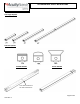
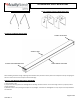
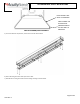
1) Feed V-hanger into holes on the Driver channel
2) Ensure supply wire is not active. If using a continuous row mount skip to steps 5-9.
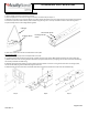
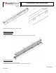
3) Remove access plate screw as shown below. Input wires will be attached to the access plate. Remove the necessary knockout(s)
and connect input wires black to black, white to white and green to green. Use only UL listed connectors rated 75C or greater.
Purple and Gray wires are low voltage dimming leads.
4) Push wires into Driver channel and reattach the access plate.
For Continuous Row
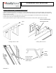
5) Remove Housing End Cap near access plate with one screw.
6) If supplied with a PLR (continuous row wiring), pull PLR connector from fixture. Male will be located on the access plate side.
7) Attach Continuous row mounting bracket into fixture A (supplied with fixture) by snapping into the driver channel and attaching
two screws provided in hardware bag.
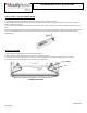
8) Remove Housing End Cap away from access plate from fixture B with one screw. If using a PLR continuous row wiring system,
connect female PLR plug into the Male PLR plug from fixture A.
9) Snap fixture B into the continuous row bracket and attach using the remaining two screws from the hardware bag.
Step 6 Step 8 Step 9
Access Plate Screw
V-Hanger
V-Hanger Holes
Housing End Cap
Screw