READ THESE INSTRUCTIONS AND SAVE THEM FOR FUTURE USE Installation Guide For models: WE52BNK5LR WE52EB5LR Table of Contents: Safety Tips. pg. 1 Unpacking Your Fan. pg. 2 Parts Inventory. pg. 2 Installation Preparation. pg. 3 Hanging Bracket Installation. pg. 3 Fan Assembly. pgs. 4 - 5 Wiring. pg. 6 Canopy Assembly. pg. 6 Blade Assembly. pg. 7 Light Kit Assembly. pg. 7 Remote Control Operation. pg. 8 Testing Your Fan. pg. 9 Troubleshooting. pg. 10 Parts Replacement. pg. 10 Warranty. pg.
SAFETY TIPS. WARNING: To reduce the risk of electrical shock, turn off the electricity to the fan at the main fuse box or circuit panel before you begin the fan installation or before servicing the fan or installing accessories. 1. READ ALL INSTRUCTIONS AND SAFETY INFORMATION CAREFULLY BEFORE INSTALLING YOUR FAN AND SAVE THESE INSTRUCTIONS. CAUTION: To avoid personal injury, the use of gloves may be necessary while handling fan parts with sharp edges. 2.
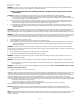
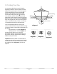
1. Unpacking Your Fan. Carefully open the packaging. Remove items from Styrofoam inserts. Remove motor housing and place on carpet or Styrofoam to avoid damage to finish. Do not discard fan carton or Styrofoam inserts should this fan need to be returned for repairs. Check against parts inventory that all parts have been included. 2. Parts Inventory. c b a a. canopy. 1 piece b. hanging bracket. 1 piece e d c. downrod and hanging ball (with pin and clip). 1 piece d. motor housing. 1 piece f e.
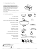
3. Installation Preparation. To prevent personal injury and damage, ensure that the hanging location allows the blades a clearance of 7 feet (2.13m) from the floor and 30in. (76cm) from any wall or obstruction. This fan is suitable for room sizes up to 400 square feet (37.2 square meters). 12ft. - 20ft. (3.66m - 6.1m) blade edge 30 7 feet inches (2.13 m) (76 cm) This fan can be mounted with a downrod on a regular (no-slope) or vaulted ceiling.
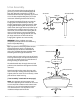
. Fan Assembly. If you wish to extend the hanging length of your fan, you must remove the hanging ball from the downrod provided to use with an extended downrod (sold separately). [If you wish to use the downrod provided, please proceed to instructions following the dotted line below.] To remove hanging ball, loosen set screw on hanging ball and remove the pin and clip. Lower hanging ball and remove stop pin.
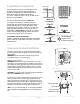
5. Fan Assembly. (cont.) With the hanging bracket secured to the outlet box and able to support the fan, you are now ready to hang your fan. Grab the fan firmly with two hands. Slide downrod through opening in hanging bracket and let hanging ball rest on the hanging bracket. Turn the hanging ball slot until it lines up with the hanging bracket tab. hanging bracket tab hanging ball slot WARNING: Failure to align slot in hanging ball with tab in hanging bracket may result in serious injury or death.
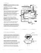
. Wiring. WARNING: Turn off circuit breakers to current fixture from breaker panel and be sure switch is turned to the OFF position. ground (green or bare) white supply wire black supply wire CAUTION: Be sure outlet box is properly grounded and that a ground wire (GREEN or Bare) is present. ground (green or bare) blue black white black white Make sure all electrical connections comply with Local Codes or Ordinances and the National Electrical Code.
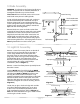
9. Blade Assembly. WARNING: To reduce the risk of serious bodily injury, DO NOT use power tools to assemble the blades. If overtightened, blades may crack and break. Time Saver: Washers for blade screws can be set on each blade screw prior to installing blades. motor housing blade attachment screws and washers Locate 15 blade attachment screws and washers in one of the hardware packs. Hold blade arm up to blade and align holes.
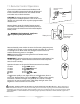
11. Remote Control Operation. Remote Control Bracket If you wish to use the remote control bracket, install screws, included in remote pack, through bracket and into the desired installation site. The remote control transmitter rests inside the bracket. Bracket Screws CAUTION: The remote control transmitter can be programmed to multiple receivers or fans. If this is not desired, turn wall switch off to any other programmable receiver or fan.
12. Testing Your Fan. It is recommended that you test fan before finalizing installation. Test fan speeds with the different fan speed buttons on remote control. Test the light ON/OFF function with the button on the remote control. Test dimmer function by holding down the button for more than 0.7 seconds. If the remote control operates all of the functions of the fan and light, battery has been installed correctly (diagram 1).
Troubleshooting. Warranty. WARNING: Failure to disconnect power supply prior to troubleshooting any wiring issues may result in serious injury. Problem: Fan fails to operate. Solutions: 1. Check wall switch to fan. 2. Verify that reverse switch is set completely in either direction. 3. Check to be sure fan is wired properly. 4. Verify battery was properly installed in remote control transmitter. 5. Repeat instructions for remote control transmitter, Step 11, page 8, fifth paragraph.