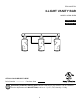
ITEM #1055721 3-LIGHT VANITY BAR MODEL #VB18-3BZW Français p. 10 Español p. 19 ATTACH YOUR RECEIPT HERE Serial Number Purchase Date Questions, problems, missing parts? Before returning to your retailer, call our customer service department at 1-800-527-1292, 8:30 a.m. - 5 p.m., CST, Monday - Friday.
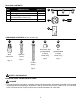
PACKAGE CONTENTS PART A B C D DESCRIPTION QUANTITY Fixture Mounting Plate Socket Ring (preassembled to fixture (A)) Glass Shade A 1 1 3 3 C B D HARDWARE CONTENTS (shown actual size) AA BB Wire Connector Machine Screw Qty. 3 Qty. 2 CC DD EE Decorative Nut (preassembled to fixture screw (CC)) Nut (preassembled to fixture screw (CC)) Qty. 2 Qty. 2 Fixture Screw Qty. 2 SAFETY INFORMATION READ AND SAVE THESE INSTRUCTIONS.
SAFETY INFORMATION DANGER • DO NOT connect this fixture to an electrical system that does not provide a means for equipment grounding. Never use a fixture in a two-wire system that is not grounded. Installing a fixture into an electrical system not having a proper grounding means could cause metal parts of the fixture to carry electrical currents if any of the fixture wires, wire connections or splices were to become broken, cut or loose during the mounting or normal operation of the fixture.
PREPARATION Before beginning assembly of product, make sure all parts are present. Compare parts with package contents list and hardware contents list. If any part is missing or damaged, do not attempt to assemble the product.
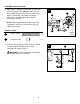
ASSEMBLY INSTRUCTIONS 3A. Remove decorative nuts (DD) and nuts (EE) from fixture screws (CC). Save decorative nuts (DD) and nuts (EE) for later use. 3A CC DD 3B. Insert fixture screws (CC) into holes in the mounting plate (B), one across from the other, as shown. Insert fixture screw (CC) heads from the opposite side of the mounting plate (B) as the GREEN ground screw head. EE 3B GREEN Ground Screw (Head) CC Hardware Used CC Fixture Screw B x2 CC DD Decorative Nut x2 EE Nut x2 4.
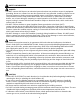
ASSEMBLY INSTRUCTIONS 5. Adjust fixture screws (CC) to proper length by screwing fixture screws (CC) completely into mounting plate (B). Temporarily place fixture (A) over mounting plate (B) to determine amount of adjustment necessary for fixture screws (CC) -fixture screws (CC) should come through holes in fixture (A) just enough so decorative nuts (DD) will fit flush against fixture (A) when mounted. Once fixture screws (CC) are adjusted, attach nuts (EE) previously removed (Step 3A, page 5).
ASSEMBLY INSTRUCTIONS 6. Unwrap BARE fixture wire from BLACK and WHITE fixture wires. Prepare wires by stripping 3/4 in. of insulation from wire ends using wire strippers (not included). 6 WHITE AA BLACK AA A Connect WHITE wire from fixture (A) to WHITE wire from outlet box using existing wire connector or wire connector (AA). Connect BLACK wire from fixture (A) to BLACK wire from outlet box using existing wire connector or wire connector (AA).
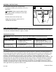
ASSEMBLY INSTRUCTIONS 8. Align holes in fixture (A) with fixture screws (CC) on mounting plate (B). [NOTE: Fixture (A) can be installed with the sockets facing either up or down.] Push fixture (A) toward wall. Attach fixture (A) to mounting plate (B) using the decorative nuts (DD). 8 CC B DD NOTE: Before tightening decorative nuts (DD) completely, use level to check fixture (A) and adjust if necessary. CC Hardware Used A DD CC Fixture Screw x2 DD Decorative Nut x2 9.
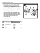
ASSEMBLY INSTRUCTIONS 10. Install three 60-watt max. standard-base incandescent bulbs (not included) or CFL/LED equivalent. 10 A WARNING: When replacing bulbs, allow bulbs, glass shades and fixture to cool down before touching. Restore power and test fixture (A). If lights do not function, please refer to TROUBLESHOOTING. Bulb CARE AND MAINTENANCE • Shut off main power supply. Wipe fixture with soft, damp cloth. Use window cleaner to clean glass. Do not use an abrasive cleaner on glass or fixture.