ITEM #0708569 FIELDER CEILING FAN MODEL #JP13EB6CRS Español p. 18 LISTED For Damp Location E192641 ATTACH YOUR RECEIPT HERE Serial Number Purchase Date Questions, problems, missing parts? Before returning to your retailer, call our customer service department at 1-800-527-1292, 8:30 a.m. - 5 p.m., CST, Monday - Friday.
TABLE OF CONTENTS Safety Information .................................................................................................................2 Package Contents .................................................................................................................4 Hardware Contents ...............................................................................................................5 Preparation .....................................................................................
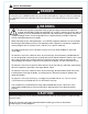
SAFETY INFORMATION DANGER If using this fan in a DAMP location, this fan must be connected to a supply circuit that is protected by a Ground Fault Circuit Interrupter (GFCI) to reduce the risk of personal injury, electrical shock or death. WARNING To reduce the risk of fire, electrical shock, or personal injury, mount fan to outlet box marked "ACCEPTABLE FOR FAN SUPPORT OF 35 LBS. (15.9 KG) OR LESS" and use mounting screws provided with the outlet box.
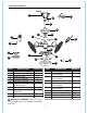
PACKAGE CONTENTS C J G A B L H F I E M D K N T P O U Q R S PART A B C D E F G H I J K DESCRIPTION Downrod Canopy Mounting Bracket Motor Assembly Pin (preassembled) Clip (preassembled) Canopy Mounting Screw (preassembled) Canopy Cover Remote Control Transmitter Remote Control Receiver Battery QUANTITY 1 1 1 1 1 1 2 1 1 1 1 PART DESCRIPTION QUANTITY L Yoke Cover 1 M Safety Cable 1 (preassembled) N Motor Plate Screw 3 (preassembled) O Light Kit Fitter Plate 1 P Light Kit Fitter Plate Screw
HARDWARE CONTENTS (shown actual size) AA E3 Wire Connector Qty. 10 PREPARATION Before beginning assembly of product, make sure all parts are present. Compare parts with package contents list and hardware cantents list. If any part is missing or damaged, do not attempt to assemble the product.
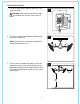
INITIAL INSTALLATION 1. Turn off circuit breakers and wall switch to the fan supply line leads. 1 DANGER: Failure to disconnect power supply prior to installation may result in serious injury or death. ON ON FF OFF O 2. This fan can only be mounted with the downrod in the motor assembly (D). 2 NOTE: Angle mount or closemount configurations are not available for this fan. 3. Check to make sure outermost edge of small fans will be at least 30 in. from any obstruction.
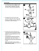
INITIAL INSTALLATION 4. Secure mounting bracket (C) to outlet box (not included) using screws, spring washers, and flat washers provided with the outlet box. *NOTE: It is very important that you use the proper hardware when installing the mounting bracket (C) as this will support the fan. 4 C FAN MOUNTING 1. Remove pin (E) and clip (F) from yoke at top of motor assembly (D) and partially loosen preassembled set screws.
FAN MOUNTING 2. Insert downrod (A) through canopy (B), canopy cover (H) and yoke cover (L). [NOTE: Canopy cover (H) must be turned with the shiny side toward the motor assembly (D).] Thread wires from motor assembly (D) through downrod (A). 2 A B H L 3. Slip downrod (A) into yoke at top of motor assembly (D), align holes and re-install pin (E) and clip (F). Re-tighten set screws in yoke and then tighten nuts. Slide yoke cover (L) down until it rests on top of motor assembly (D).
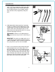
FAN MOUNTING 5. If you decided to cut back the lead wires in Step 4, strip a 1/2 in. of insulation from end of white wire. Twist stripped ends of each strand of wire within the insulation with pliers (not included). Repeat Step 5 for black, blue (if applicable) and green wires. 5 6. Slide downrod (A) through opening in mounting bracket (C) and then turn the downrod (A) so the straight edges at the top of the downrod (A) align with the sides of the mounting bracket (C).
WIRING WARNING: To reduce the risk of fire, electrical shock, or personal injury, wire connectors provided with this fan are designed to accept only one 12-gauge house wire and two lead wires from the fan. If your house wire is larger than 12-gauge or there is more than one house wire to connect to the corresponding fan lead wires, consult an electrician for the proper size wire connectors to use. CAUTION: Be sure outlet box is properly grounded and that a ground (green or bare) wire is present.
WIRING 3. Gently slide remote control receiver (J) smooth side up into mounting bracket (C). Turn spliced/taped wires upward and gently push wires and wire connectors (AA) into outlet box. Let antenna from remote control receiver (J) hang to the side. 3 Antenna NOTE: The remote control included with this fan meets the following requirements: a. Not for use with solid state fans. b. Electrical rating: 120V / 60 Hz; motor amps:1.5 MAX.
FINAL INSTALLATION 2. Remove light kit fitter plate screw (P) located in the non-slotted hole in light kit fitter (Q) and partially loosen the other two light kit fitter plate screws (P). 2 O P CAUTION: Do NOT remove screws on light kit fitter (Q) that have washers; these are not the light kit fitter plate screws (P). Q Twist light kit fitter (Q) counterclockwise to remove it from the inside of the light kit fitter plate (O). P 3.
FINAL INSTALLATION 5. Install bulbs (R). 5 WARNING: When you need to replace bulb(s), please allow the bulb(s) and glass shade to cool down before touching them. R 6. Align slots on glass shade (S) with nodules on the inside of the light kit fitter (Q). Turn glass shade (S) clockwise until it no longer turns. R 6 Nodule (on inside) NOTE: Pull down gently on the glass shade (S) to make sure it is secured completely. Q Assembly is now complete. S Slot INSTALLING FAN WITHOUT LIGHT KIT 1.
INSTALLING FAN WITHOUT LIGHT KIT 2. Align hole on the inside of the fitter plate cover (U) with the threaded rod on the fitter plate (T). Secure fitter plate cover (U) by turning fitter plate cover (U) clockwise until it no longer turns. 2 T Assembly is now complete. Threaded Rod U AUTOMATED LEARNING PROCESS/ACTIVATING CODE CAUTION: The remote control transmitter (I) can be programmed to multiple receivers or fans. If this is not desired, turn wall switch off to any other programmable receiver or fan.
AUTOMATED LEARNING PROCESS/ACTIVATING CODE Modifications not approved by the party responsible for compliance could void the user's authority to operate the equipment. *NOTE: This equipment has been tested and found to comply with the limits for a Class B digital device, pursuant to Part 15 of the FCC Rules. These limits are designed to provide reasonable protection against harmful interference in a residential installation.
CARE AND MAINTENANCE At least twice each year, lower canopy (B) to check downrod (A) assembly, and then tighten all screws on the fan. Clean motor assembly (D) with only a soft brush or lint-free cloth to avoid scratching the finish. Clean blades in smaller fans with a lint-free cloth. IMPORTANT: Shut off main power supply before beginning any maintenance. Do not use water or a damp cloth to clean the ceiling fan.
WARRANTY LITEX LIFETIME LIMITED WARRANTY: LITEX INDUSTRIES, LTD. warrants this fan to the original household purchaser for indoor use under the following provisions: 1-YEAR WARRANTY: LITEX INDUSTRIES, LTD. will replace or repair any fan which has faulty performance due to a defect in material or workmanship. Contact Customer Service at 1-800-527-1292 to arrange for return of fan. Return fan, shipping prepaid, to Litex Industries, Ltd.