
User's Manual

User Manual Rev 1.11
Basic/Smart/Smart Plus/Intelligent Charger-32A
23
Install the charge point
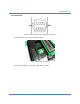
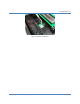
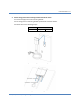
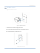
1. Secure the main body mounting bracket to the wall with appropriate screw.
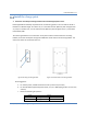
Follow applicable accessibility requirements for the mounting position. The unit shall be stored or
located at a sufficient height. For indoor site, it is not lower than 18” (450 mm) and not higher than
4” (1.2m). For outdoor site, it is not lower than 24” (600 mm) and not higher than 4” (1.2m). Refer
to Article 625, NEC.
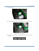
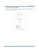
The mounting bracket has ten screw holes. If only two screws be used to fasten the mounting
bracket, the screws should pass through the middle two screw holes of the mounting bracket. The
other screw holes are reserved for the user.
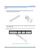
Figure 3-8 Fixing mounting bracket Figure 3-9 Screw holes of mounting bracket
Screw suggestion:
a. For masonry walls, use M6 mechanical screws. (Commercially available)
b. For finished walls supported by wood studs, use 1/4”or M6 tapping screws. (Commercially
available)
c. Please use following torque force.
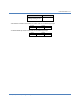
Screw
Torque
M6
25 kgf.cm min
21.7 lb-in min
#12
25 kgf.cm min
21.7 lb-in min