3rd Generation of Basic/Smart/Smart Plus/Intelligent Charger-32A User Manual Revision 1.
User Manual Rev 1.
User Manual Rev 1.11 IMPORTANT SAFETY INSTRUCTIONS This document contains instructions and warnings that must be followed when installing and using the Electric Vehicle Supply Equipment (EVSE). Before installing or using the EVSE, read this entire document as well as WARNING and CAUTION markings in this document.
User Manual Rev 1.11 Repair and Maintenance Clause • Only licensed electricians can repair or maintain the charge point. It is forbidden for general users to repair or maintain it. • Turn off input power before repair or maintenance the charge point. Federal Communication Commission Interference Statement This device complies with Part 15 of the FCC Rules.
User Manual Rev 1.11 Industry Canada statement: This device complies with ISED’s license-exempt RSSs. Operation is subject to the following two conditions: (1) This device may not cause harmful interference, and (2) this device must accept any interference received, including interference that may cause undesired operation. Le présent appareil est conforme aux CNR d’ ISED applicables aux appareils radio exempts de licence.
User Manual Rev 1.11 WARNING: RISK OF ELECTRIC SHOCK • Do not touch live electrical parts. • Incorrect connections may cause electric shock. WARNING: This equipment is intended only for charging vehicles that do not require ventilation during charging. Please refer to your vehicle’s owner’s manual to determine ventilation requirements. WARNING: Do not use extender cables to increase the length of the charging cable. Maximum length is limited to 25 feet by the National Fire Protection Agency.
User Manual Rev 1.11 Contents 1 Introduction .......................................................................................................................................... 9 Product view ............................................................................................................................... 9 2 Specifications ...................................................................................................................................... 15 Product specifications .
User Manual Rev 1.11 3.9.1 Factory settings ............................................................................................................ 41 3.9.2 Station settings............................................................................................................. 42 3.9.3 OCPP settings ............................................................................................................... 44 3.9.4 Communication settings .................................................
User Manual Rev 1.11 Customer support .....................................................................................................................
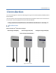
User Manual Rev 1.11 1 Introduction This user manual applies to “32A Level 2 AC Charger for Plug-in Electric Vehicles (PEVs) and Battery Electric Vehicles (BEVs)”. The Level 2 Electric Vehicle Supply Equipment (EVSE) with 32A capabilities will be used in North America. It can provide a shorter charging time than the traditional 16A EVSE. !!! Any unauthorized modifications will void the manufacturer’s warranty.
User Manual Rev 1.11 Box Contents See the table for content differences of three models.
User Manual Rev 1.11 Box Opening Process (Take Intelligent Charger-32A as example.) 1. Open the carton and remove the upper partition.
User Manual Rev 1.11 2. Take out the charge point and upturn middle partition. The charging plug is in the bottom of the carton.
User Manual Rev 1.11 3. The hook and holster is placed inside the right of the middle partition.
User Manual Rev 1.11 4. Release the bottom screw, then the wall mounting bracket can be removed.
User Manual Rev 1.11 2 Specifications Product specifications (Note: Certification in process) Table 2-1 Product specifications Item Application Voltage (Vac) Frequency (Hz) Current (Rms) Charging Connector Charging Cable Length Metering Accuracy Real Time Clock Indications Wi-Fi Cellular RFID Display Data Protocol Operation Temp. Storage Temp.
User Manual Rev 1.11 Item Web Portal Management Console Management BC3 N/A N/A Certification Basic/Smart/Smart Plus/Intelligent Charger-32A SC3 SC3+ Yes IC3 Yes UL 50/991/1449/1998/2231/2594 FCC Part 15B FCC Part 15.225 (RFID 13.56MHz) FCC Part 15.247 (WLAN 2.
User Manual Rev 1.11 3 Installation Before installation 3.1.1 Safety check CAUTION: Disconnect the power supply before installing or repairing the charge point. Failure to do so may result in physical injury or damage to the power supply system and the charge point. The charge point must be installed only by a licensed electrician in accordance with the provisions of the local electrical industry construction and should comply with national electrical codes and standards.
User Manual Rev 1.
User Manual Rev 1.11 Figure 3-1 Five screws in the Base Cover position 2.
User Manual Rev 1.11 3. Insert SIM card Figure 3-3 SIM card socket and cover Open/Close direction 3-1. Push down the cover to open SIM card socket. Figure 3-4 Open SIM card socket 3-2. Prepare the SIM card. (Use micro-SIM, 15mm x 12mm.
User Manual Rev 1.11 .
User Manual Rev 1.11 3-3. Insert the SIM card. Figure 3-6 Insert the SIM card 3-4. Close the SIM card socket and push the cover toward lock direction to lock the cover. Figure 3-7 Lock SIM card socket cover 3-5. Reassemble the top cover. Please refer to the following torque. SIM card installation is completed. Screw M4 Basic/Smart/Smart Plus/Intelligent Charger-32A 16 kgf.cm Torque 13.
User Manual Rev 1.11 Install the charge point 1. Secure the main body mounting bracket to the wall with appropriate screw. Follow applicable accessibility requirements for the mounting position. The unit shall be stored or located at a sufficient height. For indoor site, it is not lower than 18” (450 mm) and not higher than 4” (1.2m). For outdoor site, it is not lower than 24” (600 mm) and not higher than 4” (1.2m). Refer to Article 625, NEC. The mounting bracket has ten screw holes.
User Manual Rev 1.11 2. Mount charge point onto mounting bracket and lock the screw. 2-1. Put the charge point on the mounting bracket. 2-2. Fix charge point on mounting bracket by M4 screw and screw washer. 2-3. Please refer to the following torque. Screw M4 Torque 16 kgf.cm 13.
User Manual Rev 1.11 3. Plug in the power cord. (BC3/SC3 ONLY) The outlet should be located at 20-26 inch from the ground. Refer to the installation template to decide where to install the charge point.
User Manual Rev 1.11 Input cord connection (for SC3+/IC3 only) 1. Choose the appropriate conduit in accordance with all applicable state, local and national electrical codes and standards. Figure 3-13 Conduit. 2. Figure 3-14 Right angle conduit Clamp copper terminal to connect copper wire. The clamp point is covered by heat shrink tube for protecting. 2-1 Refer to the following wire specification. Use conductor type other than RHH, RHW and RHW-2 with outer covering.
User Manual Rev 1.11 3. Electrical wiring to the charge point. 3-1. Disassemble top cover. 3-2. Use Philips screwdriver to release terminal screws. 3-3. Fold the wire end to pass through the conduit and insert them into the input hole. 3-4. Fix the copper wire on the corresponding terminal block. The wiring instruction is printed in front of the terminal block (L1/L2/G). 3-5. Use the following torque to connect the wire terminal to the terminal block. Screw M4 Torque 16 kgf.cm 13.
User Manual Rev 1.11 Model Smart Charger Plus-32A Intelligent Charger-32A Current Rating 32 A 3-6. Lock the conduit on the enclosure. Please refer to the following torque. Conduit 1“ Torque 35 kgf.cm 30.36 lb-in 3-7. Reassemble top cover. Please refer to the following torque. Screw M4 Basic/Smart/Smart Plus/Intelligent Charger-32A Torque 16 kgf.cm 13.
User Manual Rev 1.11 Install the holster 1. Separate the holster from hook. Figure 3-17 Separate the holster 2. Fasten the hook on the wall with appropriate screws. 2-1. For finished walls supported by wood studs, use #12 tapping screws (x2). 2-2. The recommend torque is 25 kgf.cm (21.7 lb-in).
User Manual Rev 1.11 3. Make the holster face up and combine with the hook. Figure 3-19 Secure the holster 4. Rotate the holster down totally.
User Manual Rev 1.11 5. Keep the holster in this state and tighten screws completely. Figure 3-21 Lock screws 6. Place EV charging plug on the holster. Figure 3-22 Place EV charging plug.
User Manual Rev 1.11 Getting started (for SC3/SC3+/IC3 only) 3.7.1 Setting up the local network Firstly, connect a computer to the charge point using an Ethernet cable.
User Manual Rev 1.11 Secondly, set up a dynamic IP Address on your computer. For windows system, choose “Obtain an IP address automatically” in Internet Protocol Version 4 (TCP/IPv4) Properties dialog like the following figure.
User Manual Rev 1.11 3.7.2 Log in Open a web browser (Internet Explorer for example) and enter the IP address of SC3/SC3+/IC3. Please enter the text below in the address field of the browser and press enter. http://192.168.199.1 If “Netwrok Mode” is Gateway and “Group Use External Gateway” is No. or http://192.168.100.1 Any other “Netwrok Mode”. Now you should see the login screen: To be able to configure the charge point you should enter “admin” in the user name box.
User Manual Rev 1.11 Web-page overview (for SC3/SC3+/IC3 only) 3.8.1 Menu overview To navigate via the web browser, use the menu items available: Configuration, Maintenance, EVSE Status, LLM Status, and Security.
User Manual Rev 1.11 3.8.2 Configuration menu When you choose the Configuration menu, a sub menu will appear: ⚫ ⚫ ⚫ ⚫ The “Factory Settings” tab is used to display the information of the charge point. The “Station Settings” tab is used to set up the configuration regarding to the charge point itself. The “OCPP Settings” tab is used to set up the custom properties for uses in OCPP 1.6 services. The “Communication Settings” tab is used to set up the network connection and load management.
User Manual Rev 1.11 3.8.3 Maintenance menu When you choose the Maintenance menu, a sub menu will appear: ⚫ ⚫ ⚫ ⚫ The “Command” screen can be used to restart the charge point and reset settings to Manufacturing default. The “Charging Profile Data” screen can be used to show and clear charging profiles including “Charge Point Max Profile”, “Tx Default Profile” and “Tx Profile”. Charging Profile is defined in OCPP 1.6 specification.
User Manual Rev 1.11 3.8.4 EVSE Status When you choose the EVSE Status menu, a sub menu will appear: ⚫ The “Electric Vehicle Supply Equipment Status” can be used to show the information of EVSE. Usually these information are only for diagnostic use.
User Manual Rev 1.11 3.8.5 LLM Status menu [support only on SC3+/IC3] When you choose the LLM Status menu, a sub menu will appear: ⚫ The “Local Load Management Status” screen shows the Local Load Management (LLM) settings and current Master/Slave group member list.
User Manual Rev 1.11 3.8.6 Security menu When you choose the Security menu, a sub menu will appear: ⚫ The “Change Password” screen can be used to change the password of users for this web portal.
User Manual Rev 1.11 Configuration 3.9.1 Factory settings Clicking on the “Configuration” and then “Factory Settings” link will bring up the following screen: Basic Information Charge Point Vendor – The vendor’s name of the charge point. Charge Point Model – The model’s name of the charge point. Charge Point Serial Number – The unique serial number of the charge point. Hardware Version – The hardware version of the charge point. Firmware Version – The software version of the charge point.
User Manual Rev 1.11 Charging Connector Information Number Of Connectors – Number of connectors of the charge point. Connector Type* – Indicates type 1 or type 2 cable installed in the charge point. Max Amperage Connector – The maximum charging current of the connector capability. * A charge point may have multiple connectors installed. For our product, there is only one connector on them. 3.9.
User Manual Rev 1.11 Voltage Low – Value at which the charge point will send an under voltage warning message. Voltage High – Value at which the charge point will send an over voltage warning message. General Settings Output Power Type – AC or DC output power. In our product, this value is always “AC”. Power Phase Connected – Input power phase connected to the charge point to indicate single phase or three phases. This value is always “1”.
User Manual Rev 1.11 Plug and Charge ID – If the value is present, the charge point needs to support plug and charge scenario by using the specific identifier. If absent, authorization for each session is required. This ID must be 8 or more characters. Reservation Supported – If true, the charge point will support reservation related messages from Central System. Resume Charge After Reboot – Indicate if the charge point resumes charging after power recycle.
User Manual Rev 1.11 Clicking on the “Configuration” and then “OCPP Settings” link will bring up the following screen, since the page is too long to display, please using scrollbar to check remaining pages. On this page you can change the properties just for the charge point. Click the “Apply” button at the right side of the property when the value is changed. Remote Control Settings Remote Control Type: The remote control mode accept by SC3+/IC3.
User Manual Rev 1.11 Charge Point ID – The identity of the charge point as known in the OCPP Central System. Protocol Name – The name and version of OCPP is running in the charge point. Central System URL – The URL of the OCPP v1.6 Central System service. Basic Auth ID – The ID for BASIC authentication in HTTPS (SSL/TLS) connections. Basic Auth Password – The password for BASIC authentication in HTTPS (SSL/TLS) connections.
User Manual Rev 1.11 OCPP1.6 Settings These settings are defined and request for support in OCPP 1.6 sepcification. AllowOfflineTxForUnknownId – If set to yes, an unknown ID (not in Authorization and Cache List) will be accepted and start the charging session when charge point is not connected to central system. AuthorizationCacheEnabled – Charge point supports an Authorization Cache or not. AuthorizeRemoteTxRequests – Whether a remote request to start a transaction in the form of a RemoteStartTransaction.
User Manual Rev 1.11 HeartBeatInterval – Defines the heartbeat interval. LightIntensity – Percentage of maximum intensity at which to illuminate the charge point lighting. This value is not changeable for our product. LocalAuthorizeOffline – Whether the charge point, when offline, will start a transaction for locallyauthorizedidentifiers. LocalPreAuthorize – Whether the charge point, when online, will start a transaction for locally authorized identifiers without waiting for or requesting an Authorize.
User Manual Rev 1.11 ConnectorPhaseRotationMaxLength – Maximum number of items in a ConnectorPhaseRotation configuration key. StopTransactionOnEVSideDisconnect – When set to true, the charge point SHALL administratively stop the transaction when the cable is unplugged from the EV. StopTransactionOnInvalidId – Whether the charge point will stop an ongoing transaction when it receives a non-accepted authorization status in a StartTransaction.conf for this transaction.
User Manual Rev 1.11 StopTxnSampledData – Sampled measurands to be included in the TransactionData element of StopTransaction.req PDU, every MeterValueSampleInterval seconds from the start of the charging session. Supported value are Current.Import, Energy.Active.Import.Register, and Temperature, Voltage or any combination of these 4 value. StopTxnSampledDataMaxLength – Maximum number of items in a StopTxnSampledData configuration key. SupportedFeatureProfiles – A list of supported Feature Profiles.
User Manual Rev 1.11 ChargingScheduleMaxPeriods – Maximum number of periods that may be defined per Charging Schedule. ConnectorSwitch3to1PhaseSupported – If defined and true, this charge point supports switching from 3 to 1 phase during a charging session. This is not supported by our product since it is single phase power input MaxChargingProfilesInstalled – Maximum number of charging profiles installed at a time. 3.9.
User Manual Rev 1.11 Gateway: Use charge point as a gateway charge point. Gateway connected to OCPP 1.6 Server via cellular or Wi-Fi and connected to other charge points (called Client) via Wi-Fi and forms a local charge points group. This group is also a LAN (Local Area Network). Client: Use charge point as a client charge point. Client connected to Gateway via Wi-Fi. Client connected to OCPP1.
User Manual Rev 1.11 Gateway LAN IP – The IP of master in LAN. This value cannot be modified by users. Gateway LAN Port (SOAP) – The listen port for OCPP SOAP client server. This value cannot be modified by users. Max Group Size – The maximum number of charge points allowed in a group/LAN. This value cannot be modified by users. Gateway Serial Number – The serial number of the charge point which acts as a Gateway.
User Manual Rev 1.11 Gateway indicated by 'Gateway Serial Number' Active Device Status Active Device – Current active network device. Possible value are None, Wi-Fi or Cellular Active IP Address – Current active IP address. There will be value here only if connected to a network. Active Netmask – Current active netmask address. There will be value here only if connected to a network. Active Gateway – Current active gateway IP address.
User Manual Rev 1.11 Wi-Fi MAC Address – Display Wi-Fi device hardware MAC address. Wi-Fi Signal Strength – Display the wireless signal strength of Wi-Fi in percentage (%). Station Only – If "Station Only" is ON, the charger will stay in station mode always. If "Station Only" is OFF, it will go into AP mode after 5 times retrying to connect the external Wi-Fi AP. Note: The Station Only option only work if remote control type is OCPP.
User Manual Rev 1.11 Cellular APN – This is the gateway for all cellular traffic. Contact your cellular operator for information about this. For AT&T and Verizon LTE service, just leave it blank since the apn name is built-in in the modem. APN Username – This is the user name your ISP has assigned to you (optional). APN Password – Password to log into the ISP network (optional). Dial Number – Phone number to dial for cellular network. PIN Code – PIN code for the modem’s SIM card (optional). 4 digit number.
User Manual Rev 1.11 HINT: If user changes “Network Mode” setting, then related settings will also change automatically such as “Connectivity”, “Local Load Management”.
User Manual Rev 1.11 Note Any option followed by a star mark (*) means the setting need to reboot to take effect. When these value changed and applied the web portal will display a reminder message box for rebooting the charge point.
User Manual Rev 1.11 Maintenance This page includes some maintenance functions. 3.10.1 Reboot Command Reboot: To restart the charge point. Reset to MFG default: To reset to the factory default settings. Charging Profile Data HINT: Charging Profile is defined in OCPP 1.6 specification for smart charging.
User Manual Rev 1.11 Clear All Charging Profile Data: To clear all Charging Profile data. Local Authorization HINT: Local authorization is defined in OCPP 1.6 specification. There are two local list: Local Authorization List and Authorization Cache List. The Local Authorization List is a list of identifiers that can be synchronized with the Central System. An Authorization Cache autonomously maintains a record of previously presented identifiers that have been successfully authorized by the Central System.
User Manual Rev 1.11 Clear Local Authorization List: To clear the list of Local Authorization. Upload List: Upload a csv file which including card info to Local Authorization List. A csv file is a plain text file which each line represent a RFID card info. The format of a card info is as follow: CARD_IDTAG,EXPIRY_DATE,PARENT_CARD_IDTAG,CARD_STATUS CARD_IDTAG: 8 ~ 20 character RFID card ID tag combined with alphabet or numbers.
User Manual Rev 1.11 Clear Authorization Cache List: To clear the list of Authorization Cache. Upload Cache: Upload a csv file which including cached card info to Authorization Cache List. A csv file is a plain text file which each line represent a cached RFID card info. The format of a cached card info is as follow: CARD_IDTAG,EXPIRY_DATE,PARENT_CARD_IDTAG,CARD_STATUS,CACHED_DATE CARD_IDTAG: 8 ~ 20 character RFID card ID tag combined with alphabet or numbers.
User Manual Rev 1.11 EVSE Status To check the specific information of EVSE, you can click the corresponding buttons: Show Control Unit State: To display the information of the control unit of charge point. Mostly the function regarding to charging and safety. Show Network Unit State: To display the information of the network board of charge point. Mostly the function regarding to network connection and remote management.
User Manual Rev 1.11 LLM Status (SC3+/IC3 support only) 3.12.1 LLM information This page shows the Local Load Management information of the charge point. For more LLM description, please refer to section 3.9.4. Network Operation Mode: Indicates the charge point is in Direct mode, a Gateway or a Client. LLM Mode: Indicates Local Load Management function is enabled or disabled. Network Status: Indicates if the charge point is online or not.
User Manual Rev 1.11 3.12.2 Gateway/Client group table If the charge point is Gateway, the following LLM Group Table is present. Index: The order of the charge point. The index is first connected to Gateway first showed. Serial Number: The serial number (Charge Point Identity) of each charge point. IP: The private local IP address in LLM group of each charge point. Wire Type: The power source wire type of each charge point.
User Manual Rev 1.11 Security 3.13.1 Change password To change password, first choose user you want to change password. There are two default users – admin and maintain. Only admin user can access Security Page. Enter old password and new password then press “Apply” button to change password of the user. To reset password of all users, press “Reset password of all users” button.
User Manual Rev 1.
User Manual Rev 1.11 Authorization (for SC3+/IC3 only) Before the owner of an electric vehicle can start or stop charging, the Charge Point has to authorize the operation. 4.2.1 Online Authorization Description: • Generally, before the owner of an electric vehicle can start or stop charging, the EVSE has to authorize the operation. The EVSE SHALL only supply energy after authorization. 4.2.2 Local Authorization Description: • Synchronized with the Central System when EVSE is Online.
User Manual Rev 1.11 Charging an Electric Vehicle (EV) Choices of start charging are as below: 4.3.1 Plug and Charge 1. Insert the charging plug into the EV 2.
User Manual Rev 1.11 4.3.2 RFID card (for SC3+/IC3 only) 1. 2. 3. 4. Insert the charging plug into the EV Swipe card Waiting for authorizing Charging session started Stop charging 1. Unplug any time (disconnect the charging plug from EV to stop charging session) 2. Session ended (please return the connector to the holster) 4.4.1 Interrupt charging Please refer to STOP CHARGING section for more information. 4.4.
User Manual Rev 1.11 General care The exterior of the charge point is designed to be waterproof and dust proof. To ensure proper maintenance of the charge point, follow these guidelines: • • • • Despite the water resistance of the enclosure, when cleaning it is preferred to not direct streams of water at the unit. Clean with a soft, damp cloth. Make sure the charging plug is put back in the holster after charging to avoid damage.