
Datasheet

6/11
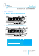
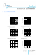
Photocouplers
MOC3020 THRU MOC3023 SERIES
Part No : MOC3020 THRU
MOC3023 SERIES
BNC-OD-C131/A4
*1 Test voltage must be applied within dv/dt rating.
*2 This is static dv/dt. Commutating dv/dt is a function of the load-driving thyristor(s) only.
*3 All devices are guaranteed to trigger at an I
F
value less than or equal to max I
FT
. Therefore,
recommended operating I
F
lies between max I
FT
, 30 mA for MOC3020, 15 mA for MOC3021,
10 mA for MOC3022, 5 mA for MOC3023, and absolute max I
F
(50mA)
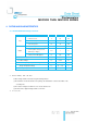
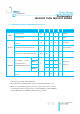
4.2 ELECTRICAL OPTICAL CHARACTERISTICS at Ta=25°C
PARAMETER
SYMBOL
MIN.
TYP.
MAX.
UNIT
CONDITIONS
INPUT
Forward Voltage
VF
—
1.15
1.5
V
IF=20mA
Reverse Current
IR
—
—
10
A
VR=6V
OUTPUT
*1 Peak Blocking Current, Either
Direction
I
DRM
—
10
100
nA
V
DRM
= 400V
Peak On-State Voltage, Either Direction
V
TM
—
1.7
3
V
I
TM
=100 mA Peak
*2 Critical rate of Rise of Off-State Voltage
dv/dt
1000
—
—
V/s
COUPLED
*3 Led Trigger Current,
Current Required to
Latch Output, Either Direction
MOC3020
I
FT
—
15
30
mA
Main Terminal
Voltage = 3V
MOC3021
—
8
15
MOC3022
—
—
10
MOC3023
—
—
5
Holding Current, Either
Direction
I
H
—
250
—
A