USER MANUAL Wi-Fi (11a/b/g/n/ac 2Tx2R) + BT (V4.1 LE) SDIO Combo Module WCBN4503M Marvell 88w8897 Version 1.3 Change History Revision Version 1.0 Date 2015/05/17 Author Ben J. Chen Version 1.1 2015/07/01 Ben J. Chen Version 1.2 2015/07/09 Ben J. Chen Version 1.3 2015/07/22 Ben J. Chen Change List Preliminary Update Transmit Output Power Update Pin Assignment - Change Pin13 to NC, using internal 1.
USER MANUAL Wi-Fi (11a/b/g/n/ac 2Tx2R) + BT (V4.1 LE) SDIO Combo Module WCBN4503M Marvell 88w8897 Version 1.3 Networking B.U. Lite-on Technology Corporation 4F, No. 90, Chien I Rd., Chung Ho, New Taipei City 235, Taiwan, R.O.C. (Signature) Customer Approval: (Title) (Company) (Date) (Please Sign Back by FAX.
CONTENT PRODUCT FEATURES ....................................................................................................................4 BT FEATURE: .........................................................................................................................................4 WI-FI FEATURE:.....................................................................................................................................4 COMMON FEATURE ......................................................
PRODUCT FEATURES BT FEATURE: l Bluetooth V4.1 LE system Backwards compatible with BT version of 1.1, 1.2, 2.0, 2.1and 3.
PRODUCT SPECIFICATIONS MAIN CHIPSET Marvell 88w8897 FUNCTIONAL SPECIFICATIONS BT Function Standard Bluetooth V4.1 LE Bus Interface SDIO Data Rate 1 Mbps, 2Mbps and Up to 3Mbps Modulation Scheme GFSK, π/4-DQPSK and 8-DPSK Frequency Range 2.402~2.480 GHz Transmit Output Power +4 ≤ Output Power ≤ +10 ; Class I Device Receiver Sensitivity < 0.1% BER at -80dBm Wi-Fi Function Standard IEEE802.11a; IEEE802.11b; IEEE 802.11g; IEEE 802.11n, IEEE 802.11ac Bus Interface SDIO 3.0 Data Rate 802.
Network Architecture Operation Channel Frequency Range Transmit Output Power – 2x2 (Tolerance: Ʋ1.5dBm) Receiver Sensitivity Ad-hoc mode (Peer-to-Peer) Infrastructure mode 2.4GHz 11: (Ch. 1-11) – United States 13: (Ch. 1-13) – Europe 14: (Ch. 1-14) – Japan 5GHz 12: United States 19: Europe 8: Japan 802.11bg 2.412 ~ 2.462 GHz 802.11a 5.15 ~ 5.825 GHz 802.11a: 14 dBm@6Mbps 14 dBm@54Mbps 802.11b: 15 dBm@1Mbps 15 dBm@11Mbps 802.11g: 14 dBm@6Mbps 14 dBm@54Mbps 802.11n(2.
-86 dBm@6Mbps -70 dBm@54Mbps 802.11n(2.4GHz): 20MHz -86 dBm@MCS0 -69 dBm@MCS7 40MHz -83 dBm@MCS0 -66 dBm@MCS7 802.11n(5GHz): 20MHz -84 dBm@MCS0 -67 dBm@MCS7 40MHz -81 dBm@MCS0 -64 dBm@MCS7 802.11ac: 20MHz -64 dBm@MCS8 40MHz -62 dBm@MCS8 -59 dBm@MCS9 80MHz -59 dBm@MCS8 -54 dBm@MCS9 WPA, WPA2, WEP 64bit & 128bit, IEEE 802.1X, IEEE 802.11i Security Common Function Operating Voltage 3.
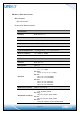
PIN ASSIGNMENT Pin. 1 2 3 4 5 6 7 8 9 10 11 12 13 14 Pin Define Description GND Ground GND SDIO_Data1 Ground SDIO Data Line1 SDIO_Data2 SDIO_Data0 SDIO_Data3 SDIO_CMD WL/BT_HOST_ WAKE# SDIO_CLK GND SDIO Data Line2 SDIO Data Line0 SDIO Data Line3 SDIO Command Input Status YES YES YES YES YES YES YES Device wake up Host, Low Active YES SDIO Clock Input Ground PDn# GND Active Low to Power-Down WLAN Ground +1.8V +3.3V 1.8V power supply for VIO_SD 3.
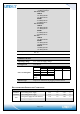
POWER-UP SEQUENCE TIMING MECHANICAL Page 9/14
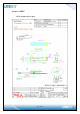
ANTENNA SPEC Wi-Fi Antenna (Q’ty: 2pcs) Page 10/14
WI-FI ANTENNA PHOTO Page 11/14
BT Antenna(Q’ty: 1pcs) Page 12/14
BT ANTENNA PHOTO Page 13/14
BLOCK DIAGRAM EEPROM INFORMATION BT Vendor ID 0xTBD Product ID 0xTBD WI-FI Region Code FCC SKU 2.
FCC Statement: Federal Communication Commission Interference Statement This equipment has been tested and found to comply with the limits for a Class B digital device, pursuant to Part 15 of the FCC Rules. These limits are designed to provide reasonable protection against harmful interference in a residential installation.
IMPORTANT NOTE: This module is intended for OEM integrator. The OEM integrator is responsible for the compliance to all the rules that apply to the product into which this certified RF module is integrated. Additional testing and certification may be necessary when multiple modules are used. 20 cm minimum distance has to be able to be maintained between the antenna and the users for the host this module is integrated into.
OEM Integrator Checklist The party below will implement the LITE-ON Module in host systems in accordance with the instructions specified in this document and the documents referenced herein. 1. The OEM integrator will ensure the Module is integrated in a host systems using only the approved antenna model(s) described in this document. 2.
IC Statement: This device complies with Industry Canada license•exempt RSS standard(s). Operation is subject to the following two conditions: (1) this device may not cause interference, and (2) this device must accept any interference, including interference that may cause undesired operation of the device. Le présent appareil est conforme aux CNR d'Industrie Canada applicables aux appareils radio exempts de licence.
Sélection dynamique de fréquences (DFS) pour les dispositifs fonctionnant dans les bandes 5250•5350 MHz, 5470•5600 MHz et 5650•5725 MHz. The maximum antenna gain permitted for devices in the bands 5250•5350 MHz and 5470•5725 MHz shall be such that the equipment still complies with the e.i.r.p. limit. le gain maximal d’antenne permis pour les dispositifs utilisant les bandes 5250•5350 MHz et 5470•5725 MHz doit se conformer à la limite de p.i.r.e.
This module is intended for OEM integrator. The OEM integrator is still responsible for the IC compliance requirement of the end product, which integrates this module. Any changes or modifications not expressly approved by the manufacturer could void the user's authority to operate this equipment. USERS MANUAL OF THE END PRODUCT: In the users manual of the end product, the end user has to be informed to keep at least 20 cm separation with the antenna while this end product is installed and operated.