
Data Sheet

LILY-W1 series - Data sheet
UBX-15000203 - R12 Interfaces Page 9 of 42
C1-Public
2 Interfaces
2.1 Host interfaces
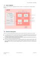
The module has two high speed host interfaces:
USB (default): USB 2.0 device interface with LPM support
SDIO: SDIO 2.0 device interface
The interface is selected by the USB/SDIO-n signal. Only one interface can be used in an application.
2.1.1 USB interface
USB is the default interface; USB/SDIO-n signal has an internal pull-up and need not be connected
while using the USB interface. See also Pin definition. The USB device interface is compliant with the
Universal Serial Bus Specification, Revision 2.0, April 27, 2000. A USB host uses the USB cable bus
and the USB 2.0 device interface to communicate with the module.
The USB device interface supports:
High/full speed operation (480/12 Mbps)
Suspend/host resume/device resume (remote wake-up)
Built-in DMA engine that reduces interrupt loads on the embedded processor and reduces the
system bus bandwidth requirement for serving the USB device operation
Link Power Management (LPM), corresponding host resume, or device resume (remote wakeup)
to exit from L1 sleep state
The USB voltage levels depend on the USB speed. See also Electrical specifications.
2.1.2 SDIO interface
LILY-W1 supports an SDIO device interface that conforms to the industry-standard SDIO
Full-Speed card specification. The SDIO is activated by pulling down the USB/SDIO-n signal. See also
Pin definition
The module acts as the device on the SDIO bus. The host unit can access registers of the SDIO
interface directly and can also access shared memory in the device through the use of BARs and a
DMA engine.
The SDIO device interface supports:
On-chip memory used for CIS
Supports 1-bit and 4-bit SDIO transfer modes at the full clock range of 0 to 50 MHz
Special interrupt register for information exchange
Card to interrupt host
The SDIO 2.0 device interface (1-bit SDIO, 4-bit SDIO transfer modes at full clock range up to 50 MHz)
supports all mandatory SDIO commands.
In 4-bit SDIO mode, data is transferred on all 4 data pins (SDIO_D[3:0]). The interrupt pin is not
available for exclusive use as it is utilized as a data transfer line. This means that if an interrupt
function is required, special timing is required to provide the interrupts. The 4-bit SDIO mode provides
the highest data transfer possible
up to 100 Mbps.
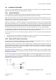
The required pull up for SD interface on SD_CMD, SD_D [3:0] should be provided by the host. The pull
up value is between 10 k to 100k
in accordance with SDIO v2.0 specifications. 33 inline resistors
may be needed to help with signal integrity. The SDIO signals levels are selectable and are relative to
the VCC_IO 1.8/3.3 voltage levels defined in Power supply interfaces.
For more information about SDIO design, see also the LILY-W1 series system integration manual [2].