
Data Sheet


LILY-W1 series - Data sheet
UBX-15000203 - R12 Antennas Page 30 of 42
C1-Public
8 Antennas
This chapter gives an overview of the different external antennas that can be fitted to the LILY-W1
series module.
This radio transmitter IC: 8595A-LILYW1 has been approved by Industry Canada to operate with
the antenna types listed below with the maximum permissible gain and required antenna
impedance for each antenna type indicated. Antenna types not included in this list, having a gain
greater than the maximum gain indicated for that type, are strictly prohibited for use with this
device.
Cet émetteur radio IC: 8595A-LILYW1 été approuvé par Industry Canada pour fonctionner avec
-dessous
liste et ayant un gain supérieur au gain maximum indiqué pour ce type-là sont strictement
ec cet appareil.
For each antenna, the "Approvals" field defines in which test reports the antenna is included.
Definitions of the «Approvals» field are:
FCC - The antenna is included in the FCC test reports and thus approved for use in countries that
accept the FCC radio approvals, primarily US.
IC - The antenna is included in the IC (Industrie Canada) test reports and thus approved for use in
countries that accept the IC radio approvals, primarily Canada.
RED - The antenna is included in the RED test reports and thus approved for use in countries that
accept the RED radio approvals, primarily the European countries.
MIC - The antenna is included in the Japanese government affiliated MIC test reports and thus
approved for use in the Japanese market.
NCC - The antenna is included in the Taiwan NCC test reports and thus approved for use in Taiwan.
In general, antennas with SMD connection, Reverse Polarity SMA connector or U.FL connector are
included in FCC, IC, MIC, NCC and RED radio tests. The antennas with SMA connector are included in
MIC, NCC and RED radio tests but not in the FCC or IC due to FCC/IC regulations.
The external antennas are connected to the board through U.FL connectors. Some antennas are
connected directly to the U.FL connector of the board while some are connected using an SMA or
reversed polarity SMA connector through a short U.FL to SMA or reversed polarity SMA adapter cable.
See also the LILY-W1 series system integration manual [2] for information about U.FL connector
design.
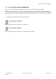
8.1 Antenna accessories
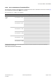
Name U.FL to SMA adapter cable
Connector U.FL and SMA jack (outer thread and pin receptacle)
Impedance 50
Minimum cable loss
0.5
dB, The cable loss must be above the minimum cable loss
to meet the regulatory requirements
. Minimum cable length
100 mm.
Comment
The SMA connector can be mounted in a panel. For
information about how to integrate the U.FL connector, see
also the LILY-W1 series system integration manual [2]
Approval RED, NCC and MIC