
Data Sheet

LILY-W1 series - Data sheet
UBX-15000203 - R12 Interfaces Page 10 of 42
C1-Public
2.2 Antenna interfaces
The LILY-W1 series supports either an internal antenna (LILY-W132 and LILY-W133) or external
antennas connected through an antenna pin (LILY-W131).
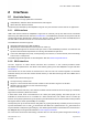
2.2.1 Internal antenna
LILY-W132 and LILY-W133 has an internal (embedded) 2.4 GHz PIFA antenna. The internal antenna
is a PIFA antenna specifically designed and optimized for the LILY form factor.
Keep a minimum clearance of 5 mm between the antenna and the casing. Keep a minimum of 10 mm
free space from the metal around the antenna including the area below. If a metal enclosure is
required, use LILY-W131 and an external antenna.
Ideally, LILY-W132 or LILY-W133 are placed so the internal antenna is in the corner of the host PCB
(with the corner closest to pin 11 in the corner). The next best option is to position the antenna side
(short side closest to the antenna) along one side of the host PCB ground plane. It is beneficial to have
a large solid ground plane on the host PCB and have a good grounding on the LILY-W132 module. The
minimum ground plane size is 24 x 30 mm, but a size of more than 50 x 50 mm is recommended.
LILY-W133 has an integrated normal SAW band pass filter, and LILY-W132 module has an integrated
LTE BAW band pass filter for optimal LTE and Wi-Fi coexistence applications.
For more information about the antenna design, see also the LILY-W1 series system integration
manual [2].
The ANT signal is not available on the solder pins of the LILY-W132 and LILY-W133 modules, and
no antenna diversity functionality is available for these variants.
2.2.2 External RF antenna interface
LILY-W131 has an antenna signal (ANT) pin with a characteristic impedance of 50 for using an
external antenna. The antenna signal supports both Tx and Rx.
The external antenna, for example, can be an SMD antenna (or PCB integrated antenna) on the host
board. An antenna connector for use with an external antenna through a coaxial cable could also be
implemented. A cable antenna might be necessary to use if the module is mounted in a shielded
enclosure like a metal box or cabinet.
An external antenna connector (U.FL. connector) reference design. The LILY-W1 series system
integration manual [2] must be followed to comply with the LILY-W1 FCC/IC modular approvals. See
also Approved antennas.
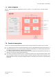
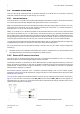
LILY-W131 also supports an antenna diversity solution with an external antenna switch, as shown in
Figure 2. The switch is controlled by the ANT_SEL and the inverse ANT_SEL-n control signals are
controlled from LILY-W131. For more information about antenna switch design, see also the LILY-W1
series system integration manual [2].
Figure 2: LILY-W131 antenna diversity solution with external antenna switch controlled by LILY-W131