
Use and Care Manual
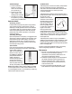


.) Oil Discharge:
a
. Connect the desired
length of /” NPTM
hose to the oil discharge
port of pump (fig. ).
b. Connect an oil control
v
alve or meter to the
discharge side of the hose.
c. The pump is now ready
for operation by attaching an air supply to the quick
connect fitting installed above.
Operation Notes:
.) Priming, suction:
In cases where the pump must prime a long distance,
such as when the pump is wall mounted, it may be
necessary to initially prime the suction hose with fluid
to be pumped. Apply air to the pump slowly at a lower
than normal operating pressure. Once the pump has
primed itself, then adjust air pressure to the desired
operating pressure.
.) Priming, discharge:
Upon initial operation of the pump, it is suggested that a
short length of hose be attached to the discharge of the
pump and then pump a small quantity of fluid into an
appropriate container prior to connecting the pump
discharge hose to its normal connection. This ensures
that the pump is fully primed.
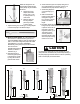
.) Foot Valve:
Due to the varying lengths of user installed suction
pipes being connected to stub pumps, models T,
T, , and
it is recommended to
install a foot valve, (fig. )
P/N (P/N for
pump models and
). This helps to
maintain pump prime and
prevents air from being
introduced into the system,
which may affect metering
accuracy and possibly cause the pump to air lock.
Note: Models T, T, T, T and
come complete with foot valves and are intended for use
in and gallon drums. It is not necessary to install any
additional foot valves in this case.
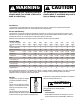
.) Relief Valve:
T
hermal expansion of fluid is an industry wide problem
that may cause leaky pipe joints, swivel leaks on
reels, meter and control handle leaks, blistered hoses
and component failures, to mention just a few
“common” problems.
Thermal expansion results from fluid expanding due to
temperature increases. This can occur most any time of
the year but is most
prevalent in the summer
and winter. In the summer,
thermal heating by the sun
may cause temperatures
near the ceiling, where oil
lines are typically located,
to reach to deg F or
higher. In the winter,
heating systems cause
ceiling temperatures to be significantly higher than
temperatures at ground level, where oil storage tanks
are located. In a closed system, there is an approximate
PSI increase in pressure for every degree F rise in
fluid temperature.
Thermal expansion valve kits, (fig. ) P/N or
are recommended for use in installations where
thermal expansion may be a problem. These kits will
prevent over pressurization by relieving excess pressure
back to the supply tank.
Contact Liquidynamics at -- if you have any
questions regarding applications or installation.
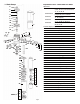
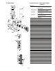
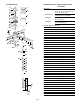
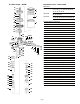
Maintenance
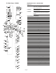
.) On a day to day basis these pumps are maintenance
free. For your future reference regarding
replacement of components, please refer to the
appropriate exploded parts diagram.
.) To maintain system integrety it is recommended to
periodically inspect all system components for
evidence of excessive wear or leaks. Particular
attention should be given to wear items such as
hoses and swivel joints.
.) Contact Liquidynamics at --, or your
local distributor for repair components and kits.
Page 5
Fig. 7
Fig. 9
Fig. 8