
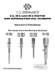
Use and Care Manual


are designed for use
w
ith gallon ( lb) drums.
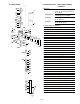
These pumps may be installed
as follows:
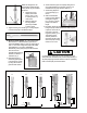
a. Attach the ” bung
adapter, P/N
(
item A, fig ), to the
” opening at the top
of the drum.
b. Slide the pump into
the bung adapter
previously installed
in step above.
c. Tighten the wing nut, item B, fig. , on bung adapter
to secure the pump at the desired height.
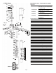
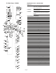
.) Universal “Stub” Pumps, fig. . Stub pumps may
be fitted with a ” NPTM extension pipe and foot
valve, P/N to adapt to most any tank situation
(use
⁄” in the case of high flow pump P/Ns
and
with
⁄” foot valve, P/N ).
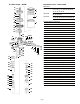
Alternatively,
these pumps may be wall mounted
with the use of an
available wall mounting
bracket,
P/N or
P/N ,
fig. .
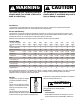
a. Determine length of
extension pipe required
to reach bottom of tank
by using the extension
pipe data chart below:
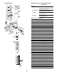
b. Attach extension pipe to stub pump taking care to
u
se a thread sealant on both ends of pipe as
i
t is
threaded into the pump and foot valve, fig. .
c. Attach bung adapter to
” tank opening, fig. ,
item A
d
. Slide the assembled
pump into bung adapter
and tighten wing nut,
fig. , item B, to secure
pump at the desired
height.
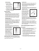
e.) Air Supply: Attach the male portion of a /” (use /”
fitting for pump models and ) air quick
coupler at the air inlet of
the pump or air filter/
regulator (item A, fig. ).
This allows a quick
and easy method to
disconnect the air supply
when the pump is being
moved or not in use.
It is important to disconnect or shut off supply air to the
pump when left unattended, this prevents the possibility of
the pump emptying the fluid container in case of a plumbing
leak or catastrophic product line failure.
CAUTION
!
Page 4
Fig. 2
Fig. 3
Fig. 4
Extension pipe data chart
5:1, 8 GPM
Length 24”
6
1
⁄2”
4
1
⁄2”
Length 21
1
⁄4”
10
1
⁄2”
9”
10
1
⁄2”
9”
3:1
Length 21
1
⁄4”
1:1
Length 27
1
⁄4”
10
1
⁄2”
9”
6
1
⁄2”
4
1
⁄2”
2
1
⁄2”
Fig. 5
Fig. 6
B
A
A
B
A
5:1
Length 27”
5:1, 12 GPM
Foot Valve P/N 950002
2
1
⁄2”
Foot Valve P/N 950047