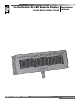
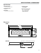
LectroCount® XL LED Remote Display E1615/E1616/E1617/E1618 Liquid Controls Group An IDEX Fluid & Metering Business Installation & Parts Operation: EM300-55
Table of Contents Introduction Bill of Materials Safety Procedures..................................................... 3 General Information.................................................. 4 Specifications............................................................ 5 Dimensions............................................................... 5 Exploded View.......................................................... 19 Bill of Materials.........................................................
Safety Procedures Be Prepared ! WARNING • Before using this product, read and understand the instructions. • All work must be performed by qualified personnel trained in the proper application, installation, and maintenance of equipment and/or systems in accordance with all applicable codes and ordinances.
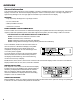
Overview General Information This manual provides instructions for the installation, operation, and maintenance of the LectroCount XL LED Remote Display. LectroCount XL LED Remote Displays display the volume of metered product in a six-digit configuration of high-intensity LED lights. The 2¼" high digits are viewable at up to 250 feet from the display.
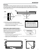
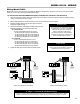
Specifications & Dimensions Specifications Temperature Range Input Signal Levels • -40 to 158 ºF (-40 to 70 ºC) • High ≥ 2.50 VDC • Lo ≤ 2.0 VDC Environmental Rating • NEMA 4X Maximum Frequency Input N/A N/A 5 kHz 5 kHz Input Voltage • 9 to 28 VDC, 500 mA maximum LectroCount LCR 600 LectroCount LCR-II LectroCount LCR LectroCount LC3 Dimensions Front 18.125" 18.125" 17.25" 17.25" 16" 16" 1.5" 1.5" 3" 3" 6" 6" Bottom .875" hole for ½" NPT cable gland or conduit fitting .
Installation Overview & Guidelines Installation Overview The LectroCount XL LED Remote Display is shipped with a 30 foot, 4-wire, shielded cable threaded through a cord grip at the bottom of the display housing and a selection of unit of display labels twist-tied to the display. Installation overview for the LectroCount XL LED Remote Display: 1. Check contents of the shipment and ensure that the correct model is included. page 4 2.
Mounting Mounting 75º 75º LED displays have an optimum viewing angle. Outside of the optimum viewing angle, displays lose contrast and become difficult to read. To supply as wide a viewing area as possible, a bias has been designed into the LectroCount XL LED Remote Display. The bias creates a optimum viewing angle offset by 75° in either direction from the horizontal and vertical perpendicular.
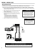
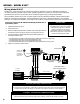
Wiring - Model E1615 Wiring Model E1615 Model E1615 of the LectroCount XL LED Remote Display is designed for use with a LectroCount LCR-II or LCR 600. LectroCount LCR-II or LCR 600 electronic registers contain a 840404, 84040, or 81920 CPU board. To wire the LectroCount XL LED Remote Display model E1615 to a 840404, 84040, or 81920 CPU board: 1. Open the LectroCount register.
Model E1616 - Wiring Wiring Model E1616 Model E1616 of the LectroCount XL LED Remote Display is designed for use with a LectroCount LCR (CPU board 81547-2) or a LC3 CPU board (Terminal Board 81924). To wire the LectroCount XL LED Remote Display model E1616 to a 81547-2 or LC3 CPU board: 1. Open the LectroCount register. Refer to the specific LectroCount register’s manual for specific instructions regarding opening, closing, and sealing the electronic register. 2.
Wiring - Model E1617 Wiring Model E1617 Model E1617 of the LectroCount XL LED Remote Display is designed to receive a calibrated (50 pulses per revolution) solid state quadrature pulse output. Typically, Model E1617 operates in conjunction with a solid state quadrature pulser (PN 077733) mounted onto a mechanical register using mounting kit (PN 47824). Since quadrature pulsers do not have an output signal to reset the LED Remote Display, a Reset Switch Kit (PN 82592) is required for this application.
Model E1618 - Wiring Wiring Model E1618 (LCMag™) Model E1618 of the LectroCount XL LED Remote Display will accept the calibrated pulse output of the LCMag HML210 converter. Since the HML210 does not have an output signal to reset the LED Remote Display, a Reset Switch Kit (PN 82592) is required for this application. The Reset Switch Kit resets the XL LED Remote Display to zero between deliveries. To wire the LectroCount XL LED Remote Display model E1618 to the HML210 Converter: 1.
Wiring - Model E1618 Wiring Model E1618 (Single Channel Pulsers) Model E1618 of the LectroCount XL LED Remote Display is designed to receive a calibrated single channel pulse output. A common application of Model E1618 is with a 100 pulses per revolution solid state single channel pulser (PN 07525) mounted onto a mechanical register using mounting kit (PN 42695). The E1618 is also compatible with any single channel pulser that meets the required specifications listed below.
Automatic Shutoff - Wiring Automatic Shutoff Wiring The LectroCount XL LED Remote Display can be wired to turn on and shut off automatically. If wired for automatic shutoff, the display will automatically turn on when a delivery is initiated. The display will remain lit until a delivery ticket is printed. When the delivery ticket begins printing, the display will automatically shut off. Only models E1615 and E1616 can be wired for automatic shutoff.
Wiring - Dual Display Kit Wiring the Dual Display Kit - PN 82594 The dual display kit allows two LectroCount XL LED Remote Displays to display the delivery volume of a single LectroCount electronic register. This dual display kit includes: • 4-port conduit box • Cord grip (2) • Nipple & seal washer To install the Dual Display Kit: 3. Remove the cord grip and cable from the port on the bottom of the unit. 4. Attach the 4-port conduit box to the empty port on the bottom of the unit. 5.
Rate of Flow Switch Kit - Wiring Wiring the Rate of Flow Switch Kit (PN 82593) - Model E1615 The Rate of Flow Switch Kit is an optional accessory that toggles the LectroCount XL LED Remote Display from the delivery volume to the current flow rate. To toggle to the current flow rate display, push select switch kit’s push button. After 5 seconds, the display will return to the delivery volume.
Wiring - Reset Switch Kit Wiring the Reset Switch Kit (PN 82592) - Models E1617 & E1618 The Reset Switch Kit (P. N. 82592) is required for the installation of XL LED Remote Display models E1617 and E1618. The reset switch resets the XL LED Remote Display to zero between deliveries. The reset switch can not zero out the totalizer while a delivery is active. To zero the display totalizer, the reset switch must be pushed when the display is not receiving a pulse output.
Decimal Place Jumper Setting Decimal Place Jumper Setting - Model E1616 The decimal place setting of model E1616 LectroCount XL LED Remote Displays is determined by the position of jumpers on the J3 and J4 terminals on the PCB. The terminals are located on the bottom of the PCB on the left side. To set the decimal place of Model E1616 LectroCount XL LED Remote Displays: 1. Remove the rear panel of the display. 2. Slide the J3 and J4 jumpers over the terminal pins in the desired position.
Torque Specifications Torque Specifications When reassembling the LectroCount XL LED Remote Display, follow the torque pattern shown below to reattach the rear panel of the display. Torque bolts to 5 to 8 in/lb.
81866 Unit of Measure Labels 81880 Cable Ass’y 84124 Digit Board (6) 08117 Screw #6-32 x .375 (2) 06639 Nut #6-32 (4) Front End Assembly 829020 (Model E1615) • 829021 (Model E1616) 829022 (Model E1617) • 829023 (Model E1618) 09363 Washer, Neoprene (16) 09364 Screw #10-24 x .
Liquid Controls 105 Albrecht Drive Lake Bluff, IL 60044 (847) 295-1050 SAMPI Via Amerigo Vespucci 1 55011 Altopascio (Lucca), Italy +39 0583 24751 IDEX Fluid and Metering Pvt. Ltd. Survey No. 256, Alindra Savli GIDC, Manjusar Dist. Vadodara 391 770 Gujarat, India +91 265 2631855 105 Albrecht Drive Lake Bluff, IL 60044-2242 1.800.458.5262 • 847.295.1050 Fax: 847.295.1057 www.lcmeter.