Operation Manual LectroCount® LCRHost™ for Windows® Operation Windows is a registered trademark of Microsoft Corp. www.lcmeter.
Table of Contents Description Page Number Translations .................................................................................. 2 Software License Agreement ....................................................... 3 Introduction .................................................................................. 4 System Components .................................................................... 5 Software Installation .....................................................................
Software License Agreement Read this license carefully. You agree that by using the itemized software package, you have agreed to the software license terms and conditions. This agreement constitutes complete and entire agreement between you and Liquid Controls with respect to this product. 1. Liquid Controls hereby grants to Licensee a nonexclusive license to use the LCRHost for Windows Software (hereinafter referred to as “Licensed Software”) 8. Termination.
Introduction LCRHost™ for Windows is an interface program for use with LectroCount® LCR® or LCR-II® Electronic Registers. Throughout this manual, LectroCount will be used to designate both the LectroCount LCR and the LectroCount LCR-II Electronic Registers. Before Getting Started: • When proving the metering system, follow pre-test and inspection procedures established by Weights and Measures authorities.
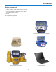
Introduction System Components The system components consist of: • Laptop Computer, which holds LCRHost™ for Windows. • LectroCount Electronic Register (LCR or LCR-II) • Flow Meter and accessories • Printer. The flowmeter/electronic register/accessory configuration is application dependent.
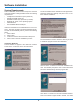
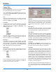
Software Installation System Requirements Prior to installation, ensure that the Computer which the LCRHost software is being installed meets the following requirements: • 10 Mbytes free hard drive space (minimum) • 256 Mbytes RAM (minimum) • 200 MHz Pentium style processor (or faster) • Windows NT, 2000, or XP operating system • CD-ROM Drive • One available RS232 serial port The second window is the “Software License Agreement”.
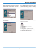
Software Installation different from the default is required by your back office software program, enter that folder here. Press “Next>” to advance to the next installation window. The last installation window indicates that the setup is complete. Click on “Finish” to complete the installation process and exit the setup program. The CD ROM may now be removed from the computer drive. The next window is for setting up the shortcuts desired.
Hardware Installation 8
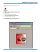
LCRHost™ Program Launch Locate the LCRLCRHost shortcut icon on the computer desktop. Double click on the Icon to launch the program. If this Icon is not on the computer desktop, follow these steps: 1. Click on “Start” 2. Click on “Run” 3. Click on “Browse” and search for folder “C:\Program Files\Liquid Controls\LCRLCRHost” 4. Click on “LCRLCRHost.exe” and click “Open” 5. Click on “OK” to launch the program.
Utilities Comm Port Port Parameters Prior to connecting to a LectroCount electronic register, the communication port must be configured. Select Comm Port from the Utilities drop-down menu. This opens the Port Parameters configuration window shown to the right. Port: Select the communication port from which the laptop computer will be communicating. The options for this setting are COM1 through COM8.
Utilities LCR Utilities Issue Command The Issue Command section of LCR Utilities allows the user to send a command or view the status of the selected LectroCount register. LCR Node # Enter the node address of the LectroCount register. Command Select a command from the List Box Window. This command will be sent to the LectroCount register when the operator clicks on Issue.
Utilities Password The Password option can be set to lock out portions of the program. This may be set before or after connecting to a LectroCount register. If a password is set, the correct password must be entered to access advanced options in the program. If the password lock is enabled, the operator will have access to the Preset and Delivery menu, but not the Calibration or Save/Load LCR Configuration menus. From the Utilities drop down menu, click on Password to open the Password window.
LCR Node Address LCR Connection Once the communications port and the node address of the LectroCount register is established, enter the LectroCount node address in the window below LCR Node. Then, click on Connect below the window. This will establish communication with the LectroCount register. The heading on the window will change from LCRView - 1 to LCR -> N, where N is the node address of the connected LectroCount register.
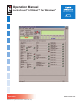
Navigating the Display The window below is displayed when a LectroCount connection is successfully established. This is the main window that an operator would utilize if a laptop computer is used on a daily basis for deliveries. Field has been updated and is editable given the current switch position of LectroCount register. Each of the fields will have a green, red, or yellow indicator next to it.
Navigating the Display LCR Node Configure LCR This is an indication of the node address of the connected LectroCount register. The display indicator represents what is currently displayed on the LectroCount register’s display. This updates once per second. This menu is not accessible if the password lock is enabled. Configure LCR has five sub-menus.
Preset and Delivery The Preset and Delivery menu contains information the operator might use on a daily basis for deliveries. This program provides more flexibility in making deliveries than the operator would have using the LectroCount register as a stand alone, pump-and-print device. Unit This field indicates the current, selected unit of measure for deliveries. This field cannot be edited from this location.
Preset and Delivery Preset Delivery The Preset Delivery section contains fields for entering preset values and for monitoring the current delivery status of a preset delivery. Presets can be entered based on Price, Gross volume, or Net volume. If temperature compensation is not enabled for deliveries, Net Preset values will be disabled. The center column of the Preset and Delivery menu is separated into three sections.
Preset and Delivery Preset Type Preset Type is used to define what happens to a preset value after a delivery is complete. Select OFF to disable Auxiliary Out 1 regardless of delivery status. Click on the green lock indicator to open a List Box Window. There are three options for Preset Type: CLEAR, MULTIPLE, RETAIN, and INVENTORY. Select ON to enable Aux 1 output regardless of delivery status. Select “MONITOR FLOW RATE” to activate Auxiliary Out 1 before each delivery.
Configure LCR - General Setup Date The Configure LCR Menu is broken down into five submenus. These are General Setup, System Calibration, Product Calibration, Diagnostics, and Security. These will be covered in the order that they appear. General Setup This field indicates the current date. Click on the green lock indicator to open a Field Edit Window. Use the up and down arrows for hour, minutes, and seconds to set the current time of day. Click on Write to LCR when the time has been set.
Configure LCR - General Setup Sale # Vol Corrected Msg? This field indicates the current sale number. The Sale # is used to track the number of transactions the LectroCount processes. This number will increment each time a delivery is started. Click on the green lock indicator to open a Field Edit Window. Vol Corrected Msg? is used to enable or disable the printing of the base temperature of net deliveries on the delivery ticket. In many applications, this is required.
Configure LCR - General Setup Header Text - 1 through 12 Header Text is information printed at the beginning of a delivery ticket. These fields may be left blank or they may contain information specified by the user. Click on the green lock indicator to open a Field Edit Window for each Header Text location. Use the alphanumeric keys to enter information to be printed that line of the ticket header. Each line can contain up to 35 characters, including spaces.
Configure LCR - System Calibration Ticket Required? The System Calibration section of General Setup is used to set parameters associated with system. These fields will not be active unless the LectroCount selector switch is in the calibration position. Some fields are not editable even when the switch is in the calibration position. This field allows the user to decide whether a delivery ticket will be required for each delivery. Most Weights & Measures governed truck applications will require a ticket.
Configure LCR - System Calibration Printer Residual “Printer” is used to select the printer model with which the LectroCount will be communicating. Selection of the wrong printer model may result in miscommunication between the printer and the LectroCount. Residual is used to select what happens to the least significant digit when a fraction of that volume has been read by the meter. Click on the green lock indicator to open a List Box Window.
Configure LCR - System Calibration Calib Distance Temperature This field is used to calibrate the odometer. This field displays the current reading from the temperature probe. If the LectroCount is not equipped with a temperature probe, the display will show dashes. This field allows entry from a Weights & Measures calibrated thermometer. To begin odometer calibration, click on the green lock indicator to open a Field Edit Window. Enter 0 for Calib Distance.
Configure LCR - System Calibration RTD Slope, RTD Offset, Last Calibration, Calibration Number, Calibration Event, Configuration Event RTD Slope and RTD Offset are used for factory calibration of the LectroCount and are not editable. The calibration information fields of Calib, Calib Number, Calib Event, and Config Event are for metrology use and are not editable. Last Calibration: Displays the date and time of the last calibration.
Configure LCR - Product Calibration Type Product Calibration fields are used to adjust individual calibration factors for each of the product codes for the LectroCount. This field is used to specify the type of product that will be delivered with the current Product Calibration being set up. Click on the green lock indicator to open a List Box Window with the options: AMMONIA, AVIATION, DISTILLATE, GASOLINE, METHANOL, LPG, LUBE OIL, and NO PRODUCT.
Configure LCR - Product Calibration Compensation Type & Parameters Product VCF Type Scale Parameter Range General Linear C Linear/degree 0 to 0.003 15 -90 N/A +100 General Linear F Linear/degree 0 to 0.005 60 -130 N/A +212 LPG (USA) API Table 24 F Base Specific Gravity 0.5 to 0.550 60 -50 -50 +140 LPG (Europe & Canada) API Table 54 C Base Density Kg/L 0.5 to 0.600 15 -46 -46 +60 Refined Petroleum Products (Europe & Canada) API Table 54B C Base Density Kg/m3 653.
Configure LCR - Product Calibration Compensation Parameter This field contains the coefficient of expansion per degree, the base temperature density, API gravity, or the base temperature specific gravity that will be used with the Compensation Type selected. Click on the green lock indicator to open a Field Edit Window. Enter the value in the for Auxiliary Multiplier and click on Write to LCR. If this value is set to zero, the Auxiliary Multiplier value will NOT print on the delivery ticket.
Configure LCR - Product Calibration Gross Quantity, Gross Preset Point Number Gross Quantity is a read-only field. It is not editable. The gross quantity of fluid measured by the meter during a product calibration prover run is represented here. This is covered in detail in the sections on Single-Point Calibration and Multi-Point Calibration. This field represents a point on the calibration curve for Multi-point Calibration. Up to 10 points on a curve may be calibrated for near perfect accuracy.
Configure LCR - Product Calibration Gross Total This field represents the cumulative, gross total for the product that is selected. Click on the green lock indicator to open a Field Edit Window and enter the Gross Total. Click on Write to LCR. Net Total This field represents the compensated, net total for the product selected. Click on the green lock indicator to open a Field Edit Window and enter the Net Total. Click on Write to LCR.
Single-Point Calibration Performing Single-point Calibration requires the use of a volumetric prover or other calibrated device with which to compare the meter delivery quantity against a standard. Since the rest of the Product Calibration information has been entered, this calibration procedure is ready to proceed. As describe on Page 28, Pulse/Unit represents the number of pulses that the LectroCount counts per unit of volume.
Multi-Point Calibration Multi-point Calibration allows a flowmeter to be used over a wide range of flow rates without experiencing a loss in measurement accuracy due to the inherent shape of the meter curve. This puts the Linearization algorithm into effect. If the error message ADJACENT POINTS OUT OF 0.25% RANGE is displayed, APPLIED will not take effect. The Linearization Points will need to be re-selected to ensure that no two adjacent points, based on flow rate, are more than 0.
Multi-Point Calibration Method 2 - Field Proving Technique In situations where the meter’s accuracy curve is not provided by the manufacturer, Multi-point Calibration must be performed by proving the meter at various flow rates. 11. Move the pointer to “Flow Rate” and press ENTER to open a Field Edit Window and enter the maximum flow rate observed during the run. Press ENTER. 12.
Diagnostics The Diagnostics screen is for viewing only. None of the fields are editable. Printer Busy? indicates that the print processor has begun to print a ticket. Diagnostics Delivery Status Pulser Faults represents the number of false or missing pulses detected during the last delivery. ROM Check? indicates if a delivery could not be started due to the checksum of the LectroCount program code space failing. Supply Voltage represents the current voltage being supplied to the system.
Diagnostics Data Access? indicates if a data access error occurred during a delivery which was critical to the delivery. New Delivery Queued? indicates that a new delivery has been queued in the LCR. This condition occurs when an "Run" command is issued and the switch is in the STOP, PRINT, or SHIFT PRINT position. Delivery Code Delivery Ticket? indicates that a delivery ticket is pending. A new delivery cannot be started until this field is cleared by successfully printing the last delivery ticket.
Security Position the pointer on “User Key” and press ENTER to open a Field Edit Window. After “User Key” has been programmed, the system can be UNLOCKED by re-entering the “User Key” password. Move the pointer to “Security” and press ENTER to open a List Box Window with the options LOCKED and UNLOCKED. To lock the system, move select LOCKED and press ENTER. To unlock the system, return to “User Key” and enter the password. “Factory Key” is for factory use only.
SAVE CONFIGURATION SCREEN 1 - “MAIN MENU” Using the arrow keys, position the pointer on “Save Configuration” and press the ENTER key. This will advance the display to the SCREEN 27 - “SAVE CONFIGURATION”. SCREEN 27 - “SAVE CONFIGURATION” (shown below) This feature allows the user of LCRHost to save the calibration parameters of a LectroCount in a file on the Laptop Computer.
SAVE CONFIGURATION SCREEN 27a - “SAVE CONFIGURATION” Enter a file name that will reside on the Laptop Computer and contain the calibration data of the LectroCount. SCREEN 1 - “MAIN MENU” Using the arrow keys, position the pointer on “Load Configuration” and press the ENTER key. This will advance the display to the SCREEN 28 - “LOAD CONFIGURATION” (Page 90).
LOAD CONFIGURATION SCREEN 28 - “LOAD CONFIGURATION” Loads a LectroCount with the calibration data previously saved with the “Save Configuration” option. SCREEN 28a - “SAVE CONFIGURATION” Enter a file name that will reside on the Laptop Computer and contain the calibration data of the LectroCount.
Index Return to Table of Contents 42
Index Return to Table of Contents 43
A Unit of IDEX Corporation 105 Albrecht Drive Lake Bluff, IL 60044-2242 1.800.458.5262 • 847.295.1050 Fax: 847.295.1057 www.lcmeter.com © 2004 Liquid Controls Pub. No.