Installation & Parts Manual V-7 Valves Installation: M400-10 www.lcmeter.
Table of Contents Description Page Number Publication Updates and Translations General Information ...............................................2 Application Class Description ................................2 Specifications .........................................................3 How V-7 Valves Work .............................................3 Accessories ............................................................4 New Installations ....................................................
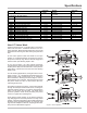
Specifications Model Body & Seal Material Companion Flanges V-7 (A2600 Series) Used with M-5, M-7 & M-10 Meters Working Pressure Application Class* 150 PSI (10.3 BAR) A2621 Aluminum with Viton Seal 1½" & 2" 150 PSI (10.3 BAR) A2623 Aluminum with Teflon Seal 1½" & 2" 150 PSI (10.
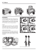
V-7 Valves Figure 3a: Cast Iron or Aluminum Figure 3b: Stainless Steel Figure 3c: Brass Accessories Dashpot Washers V-7 Valves are offered with a variety of dashpot washers. They are available in either brass or stainless steel construction material. Four different bleed orifice configurations (Figure 4) are available to ensure proper closure regardless of viscosity. For viscosities greater than 20,000 SSU, do not use a dashpot washer.
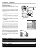
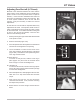
V-7 Valves - Installation New Installations When ordered with a new metering system, the V-7 Series Valve is supplied mounted to the outlet side of the meter as shown to the right. A liquid line must be connected to the flange on the outlet side of the valve or to the accompanying air check valve. The flange connection on the V-7 valve is 1½” or 2” BSPT or NPT or weld type.
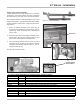
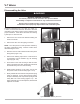
V-7 Valves - Installation Retrofit Installations (continued) Attaching the Valve Handle There are several options for valve handles. Systems which do not use a preset use a faucet valve kit (Part Number A2755). For systems which use a preset, curved valve handles are offered for left-to-right or right-to-left flow, or a straight handle may be used. The valve handle options are listed in the table below. 1. Line up the hole in the valve handle with the holes in the lift bracket. 2.
V-7 Valves - Installation Installing the Linkage Assembly Linkage assemblies are used with presets. The linkage provides the connection between the valve handle and the preset trip ring mounted on the mechanical register. The linkage assembly is selected based on the meter/ register configuration. Linkage assemblies are available in either straight or offset styles. These are listed in the table below. Figure 12: Linkage Assemblies 1.
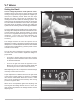
V-7 Valves Setting the Dwell Correct linkage adjustments avoid hydraulic shock. Hydraulic shock occurs when a volume (mass) of liquid moving at a high rate through a pipeline is stopped by a valve that is suddenly closed. When the flow stops abruptly, the mass of liquid acts as a battering ram, causing a shock effect within the metering system. The meter housing and internal parts receive the full impact since the valve is located at the meter outlet.
V-7 Valves Adjusting Zero Shut-off (LC Preset) Because of the interaction between the valve and the preset counter, some adjustment may be needed to the preset counter so that components work at optimum efficiency. Preset Counters assembled with meters at the factory are adjusted for proper shut-off timing. Due to meter system variations, such as flow rate and viscosity, it may be necessary to make zero shut-off adjustments. At least two test runs should be completed before any adjustments are made.
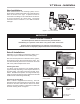
V-7 Valves Disassembling the Valve ! WARNING Relieve Internal Pressure All internal pressure must be relieved to zero pressure before disassembly or inspection of the meter or any of the meter accessories. Serious injury or death from fire or explosion could result from maintenance of an improperly depressurized and evacuated system. To perform maintenance on a V-7 valve, or to repair a V7 valve, it must be removed from the meter.
V-7 Valves Disassembling the Valve (continued) Disassembling the Piston Assembly 8. Use a 7/16” wrench to remove the nut from the valve shaft (Figure 18a). 9. Remove the nut, washer, spring, dashpot washer, and piston from the valve shaft (Figure 18b). Reassembling the Valve 1. Place the piston on the valve shaft. 2. Place the dashpot washer, spring, and washer on the valve shaft and secure by placing the nut on the end of the valve shaft. 3. Place the compression spring into the valve housing.
Illustrated Parts Breakdown - V-7 Aluminum Valves A2655 Shown Item No. 110 133 220 318 337 354 370 380 382 453 465 516 532 553 564 572 606 626 724 727 738 M ode l Num be r Ite m No. 110 133 220 318 337 354 370 380 382 388 424 446 453 465 516 532 553 564 572 606 626 724 738 780 Description Part No.
Illustrated Parts Breakdown - V-7 Brass Valves A2690 Shown Item No. 110 133 220 310 318 337 354 370 380 382 453 465 516 532 553 564 572 606 626 738 724 Model Number Item No.
Illustrated Parts Breakdown - V-7 Cast Iron Valves A2672 Shown Item No. 110 133 220 318 337 354 370 380 382 388 424 446 465 512 516 532 553 564 572 606 626 724 738 780 Model Number Item No.
Illustrated Parts Breakdown - V-7 Stainless Steel Valves A2682 Shown Item No. 133 208 220 318 337 354 370 380 381 382 383 388 424 446 461 463 465 532 550 553 561 564 570 572 606 626 724 738 781 Model Number Item No.
A Unit of IDEX Corporation 105 Albrecht Drive Lake Bluff, IL 60044-2242 1.800.458.5262 • 847.295.1050 Fax: 847.295.1057 www.lcmeter.com © 2006 Liquid Controls Pub. No.