
Owner's manual


Sponsler, Inc.
T650N Series Cryogenic Truck Totalizer
pg
5
DOC# MN-650
Initial System Start Up Procedure
Assure all Field Terminations are complete, correct and secure. Turn on the T650N and observe that 8 zeros are
displayed and the LCD backlighting is on. Depress reset if external reset option was selected.
Refer to DWG. # SCI-T650N-REV C-TC-INT
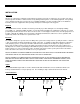
Open the T650N enclosure and depress “System Test” S9. All LED indicators of the 10 position bar graph D1-D10
should be illuminated except D3 if “1” is selected by “0-1” Switch S2. Also observe that both the LCD counters
increment equally. D4, 5, 6, & 7 will blink. Each LED indicates a specific T650N function. The indicators are
extensively discussed in the Description Section and in the Troubleshooting Section which should be referenced in the
event of a failure of the T650N.
Switch, Adjustment, and Display Descriptions
S1 - Power Switch: 3 Amp DPDT; switches fused input power to the logic circuits of the factoring and
display boards.
S2 - “0-1” Switch: 2 position D.I.P.; permits increased calibration accuracy when the calibration factor
begins with a ‘1’ such as .015979 (Refer to example #3).
S3-6 - Factoring Switches: 10 position (0-9) BCD rotary; inserts the desired calibration factor digitally with S3 as
the MSD & S6 as the LSD.
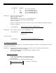
S7 - Divider Switch: 5 position rotary; provides the proper divider for decimal point placement in the
calibration factor.
Position 1=1, 2=10, 3=100, 4=1000, 5=10000
S8 - Reset Switch: Single pole, momentary pushbutton; resets display and all logic circuits when
depressed and released.
S9 - System Test: Single pole, momentary pushbutton; activates LED bar graph and injects 500 Hz signal
to increment LCD counters while depressed.
S10 - Display Test: Single pole, momentary pushbutton; injects signal to increment large LCD while
depressed.
S11 - Display Decimal Point: Display Blanking & Backlight Control: 2 position, 4 pole D.I.P.
S11-1: displays 10ths Decimal Point when in ‘1’ position
S11-2: displays 100ths Decimal Point when in ‘2’ position
S11-3: display blanks when in ‘3’ position and power “OFF”
S11-4: extinguishes backlight when in ‘4’ position and power “OFF”.
S12 - TC Selector: 2 position D.I.P.; permits by-pass of the temperature compensation module. Positions
0=w/o TC; 1=TC incorporated.
R1 - Sensitivity Adjustment: Single turn potentiometer; establishes input signal amplitude required to initiate the
count sequence.
CCW = minimum sensitivity CW = maximum sensitivity