
User Manual

6
Bolt Size
Foot-Pounds
NOMINAL*
Newton-Meter
NOMINAL*
Foot-Pounds
NOMINAL*
Newton-Meter
NOMINAL*
#8 (.164) - 32 UNC-2A 2.54 (30.5 in/lb) 3.4
#10 (.190) - 24 UNC-2A 3.75 (45 in/lb) 5.1
1/4” (.250) - 20 UNC-2A 7.3 9.9 12.5 16.9
5/16” (.3125) - 18 UNC-2A 15.3 20.7 26 35.3
3/8” (.375) - 16 UNC-2A 27 37 44 59.7
7/16” (.4375) - 14 UNC-2A 43 58 68.5 92.9
1/2” (.500) - 13 UNC-2A 66 90 112 152
5/8” (.625) - 11 UNC-2A 132 179 222 301
3/4” (.750) - 10 UNC-2A 233 316 395 535
*Torque Tolerance is ± 10%
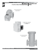
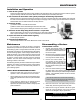
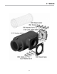
1. Strainer baskets have an extended collar, or lip on the
bottom end of the basket (C). Insert this end into the
strainer housing rst.
2. Place the o-ring (1) in
the groove on top of
the strainer housing
(2).
3. Place the center hole
of the basket cover
plate (3) over the
basket rod (4) that
extends from the
center of the housing.
The plate should now
rest on top of the
basket.
4. Install the washer (5)
and the wing-nut (6)
on the basket rod (4).
5. Place the cotter pin (7)
through the hole at the
top of the basket rod (4).
6. Place the cover (8) on top of the strainer housing.
7. Insert the 12 or 16 screws (9) into the cover holes (8).
Attach the at washer (10) and nuts (11) to the screws (9)
from below. Evenly tighten all nuts and screws. See Torque
Chart below.
Before re-lling or re-pressurizing your meter/strainer assembly, all seal gaskets and bolts must be in place
and fully tightened to prevent leakage of product out of the system. See Torque Chart below. Failure to follow
this procedure may result in a hazardous condition and possible serious injury or death.
!
Leakage that occurs after tightening the fasteners
indicates a damaged seal, or distortion to the surface
of the cover. In either case, the seals or cover must be
replaced. Excessive tightening will not stop the leakage.
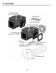
Tightening Screws and Nuts
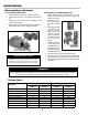
1. Replace the strainer basket (A) or (B) into the housing.
2. Place the end cover o-ring (1) in the groove in the end cover
(2).
3. Place the end cover (2) with the o-ring installed, on the
strainer housing end (3).
4. Fasten the end cover with the 4 washers and screws (4).
Evenly tighten all screws. See Torque Chart below.