
Manual

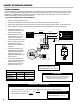


The 3-wire TTL Sourcing conguration translates the output signal from the turbine owmeter’s pickup coil into a
voltage value. The output of the 3-wire TTL Sourcing conguration is driven either positive or negative internally. Note
that the name “TTL” is misleading because the output switches from 0V to +Vs, not 0V to +5V as the TTL standard
indicates. In the SP714-S2i, “TTL” indicates that the output is driven in both the positive and zero volt cases. A pull-
up or pull-down resistor is optional in the 3-wire TTL Sourcing conguration; however, a resistor can be installed to
prevent damage from faults.
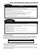
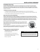
1. Remove the SP714-S2i housing cover.
2. Pull the SP714-S2i board from the housing for access to the TB1 terminal block and the S1 switches.
3. Attach proper cable glands and/or conduit connectors to the SP714-S2i, the pulse acquisition device, and DC power supply.
4. Run the wires (through proper conduit) between the SP714-S2i, the pulse acquisition device, and DC power supply.
5. Set the rst S1 switch to the ON position and the second S1 switch to the ON position.
6. Splice the resistor onto the +V
leg from the DC power supply.
This step is optional. The value of the
resistor can be determined using the
information below.
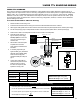
7. Wire the SP714-S2i to the pulse
acquisition device and DC
power supply as indicated in the
schematic.
8. If necessary, adjust the input
signal sensitivity (R1), activate the
diagnostic test oscsillator (SW2),
and/or check the diagnostic
operational LEDs (D1 & D2). See
page 11.
9. Coil the wires underneath the
CPU board and place the board
inside the housing, ensuring
the wires are not pinched, and
replace the housing cover.
S1
ONON
1
2
GND
1
3 2 1
Signal
+V
0V
S1
Signal Ground
Position 1 - ON
Position 2 - ON
ONON
1
2
DC Power
Supply
Resistor (RP)
Electronic Register
or
Flow Computer
Chassis GND
Cable Shield
3 2 1
2 1
TB2
Pickup Coil Signal
TB1
INTERNAL OPERATING PRINCIPLE
optional
Three
Conductor
Shielded
Cable
Connect Chassis GNDs at pulse acquisition device only
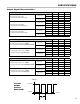
SP714-S2i Connections
Pulse Acquisition Device
Sponsler IT 400 TB2 (1) TB2 (2)
LectroCount
LCR-II/LCR 600
J8 (33) J8 (37)
Toptech MultiLoad TB2B (V+ any) TB2B (V COM any)
Maximum Cable Length: 1000 m (3280’)
Minimum Wire Gauge: 0.75 mm
2
(18 AWG)
Limit total system current to 50 mA Imax =
For 24 VDC operation pulse acquisition device impedance must be at least 1200 Ω
For 5 VDC operation pulse acquisition device impedance must be at least 250 Ω
Resistor (RP) Power Dissipation P =
Resistor Value - 3-wire TTL Sourcing
24 VDC Power Supply: Rp = 680 Ω, 1 W
12 VDC Power Supply: Rp = 330 Ω, 1 W
5 VDC Power Supply: Rp = 12 Ω, 2.5 W
Recommended Resistor Value (Rp)
Vdc
RP
(V)
2
RP
9