
Manual


INSTALLATION OVERVIEW
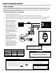
In order to maintain IECEx compliance, the SP714-S2i is shipped as part of an assembly with a Sponsler turbine
owmeter. A complete installation of the owmeter and pulse amplier assembly includes the physical installation of
the owmeter and the electrical installation of the SP714-S2i. Guidelines for the physical installation of the owmeter
can be found in the Sponsler turbine owmeter manual. Instructions for the electronic installation of the SP714-S2i are
included in this manual.
1. Install Sponsler turbine owmeter (with SP714-S2i) into system piping. Sponsler Turbine Flowmeter Installation Manual
2. Wire the SP714-S2i to a pulse acquisition device and set the S1 switches to the preferred output signal characteristics. Page 7
3. Perform eld test and adjust the input signal sensitivity (if necessary). Page 11
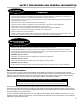
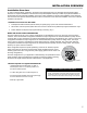
Use the proper cable glands, conduit connectors, cables,
conduit, and installation procedures when wiring the SP714-S2i.
Installations must be in full accordance with national and local
codes to maintain the hazardous location ratings on the product.
Observe National and Local Codes
WIRING THE OUTPUT SIGNAL CONFIGURATIONS
The SP714-S2i can be set to one of three congurations: 2-wire Standard, 3-wire TTL Sourcing, and 3-wire Open
Collector. The 2-wire Standard conguration translates the output signal from the turbine owmeter’s pickup coil into
a current value. 2-wire connections are effective transmitting the signal over long distances. The 3-wire TTL Sourcing
conguration translates the output signal from the turbine owmeter’s pickup coil into a voltage value. The output
of the 3-wire TTL Sourcing conguration is driven either positive or negative internally. The 3-wire Open Collector
conguration translates the output signal from the turbine owmeter’s pickup coil into a voltage value. The output is
driven by an “Open Collector” transistor.
Each conguration requires a specic positioning of the two S1 switches, specic
wiring connections (to the power supply and the pulse acquistition device), and a
resistor(s) spliced into the +V leg from the power supply (optional for the 3-wire TTL
Sourcing conguration).
The best conguration for your application is determined by the specications of the
pulse acquistion device (typically a ow computer or electronic register) receiving
the SP714-S2i signal and the electrical characteristics of the application.
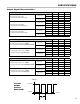
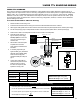
SW1
S1
JU4
D1
D2
GND
TB2
S2
R1
TB1
ONON
1
2
GND
1
S1 Switches
• 18 AWG stranded wire in shielded cable, UL Listed For
ambient temperatures above 70°C, use eld wiring suitable for 20°C
above maximum ambient temperature.
• ½-14 NPT cable glands Use Ex d certied cable glands only.
• Connectors for pulse acquisition device or DC power supply
See “Observe National and Local Codes” on this page.
• PTFE tape or pipe sealant
7