
Manual

45
8-10.5 RS232/RS422 16 Point Serial Input
Example
Example : (S) = Space
Transmit from terminal Receive from Batcher
D11(S) [Unit 7 activated] Device #11
FC(S)500(S)KC(S)305 FC 500 KC 305
{Frequency for C (Point 03) is set to 500,}
{K Factor for C (Point 03) is set to 305.}
FC(S)KC(S)(ENTER) FC KC
{Unit echoes back commands as sent.}
Frequency of C is sent 500
K Factor of C is sent 305
8-11 Strobe Address Operation
Another method of reading the status of a unit
with either a RS232 or RS422 option is by
means of a separate strobe address and a 3
bit data request code. The strobe address
method does not allow changes of set points.
Theoretically hundreds of units could be
linked together to transmit data from the
Batchers over a serial transmit line. The
units could be assigned any code number
except "00".
The 3 bit data request code would be latched
in at the positive edge of a 3 to 30 VDC strobe
input that remained high a minimum of 25 mil-
liseconds. Requests are processed on a non-
priority basis. Normally data will begin to be
transmitted from the Batcher over the RS232
or RS422 serial transmit lines within 5 msec
unless interrupted by a keypad entry or other
signal input.
Note: No other unit should be brought on line
until data requested has been transmit-
ted.
Note: There are no allowances for Frequency
or K Factor access on units with the 16
Point Option.
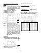
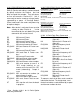
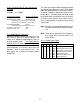
8-11.1 Strobe Input Codes
# DL4 DL2 DL1 Code Description
0 0 0 0 PA Will transmit Preset value.
1 0 0 1 PW Will transmit Prewarn value.
20 1 0 KC
Will transmit counter K Factor.
3 0 1 1 KR Will transmit Rate K Factor.
4 1 0 0 DC Will transmit Count.
5 1 0 1 DT Will transmit Grand Total.
6 1 1 0 DR Will transmit Rate.