
Manual

10
Installation
Wiring
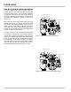
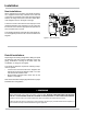
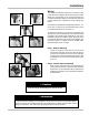
Step 3 - Reassemble Cable Plug
Reinstall the terminal block into the cable plug housing in
the same orientation you found it. Tighten the strain relief
strap inside the cable plug using the two screws. Tighten the
cable gland on the bottom of the cable plug so that it seals
around the cable.
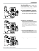
Reconnect the cable plug to the coil. Place the cover over
the cable plug and fasten with the screw to a torque of 8.8
in-lbs (1 Nm).
LC
3
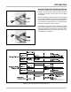
Connections
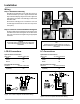
Optical Sensor Connection
Wire Color J11 Pin Connection
Red 33
White 34
Black 35
S3 Solenoid Connection
Terminal J11 Pin Connection
1 (Red) 31
2 (Black) 32
Figure 11a: LCR-II to Optical Air Eliminator Wiring
Figure 11b: LC³ to Optical Air Eliminator Wiring
LC³
ConnectthewirestoterminalblockJ11ontheLec-
troCountCPUboard.RefertoFigure11bforadditional
clarication.
LCR-II
ConnectthewirestoterminalblockJ15ontheLectro-
CountCPUboard.RefertoFigure11aforadditional
clarication.
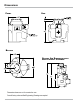
Step 4 - Connect to LectroCount Electronic Register
Route the cables from the optical sensor and solenoid valve
to the back of the LectroCount register. Connect these to two
open ports on the back of the register using the appropriate
connectors.
LCR-II
Connections
Optical Sensor Connection
Wire Color J15 Pin Connection
Red 56
White 55
Black 54
S3 Solenoid Connection
Terminal J15 Pin Connection
1 (Red) 52
2 (Black) 53