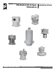
Mechanical Air & Vapor Eliminators Liquid Controls Group An IDEX Fluid & Metering Business Installation & Parts Installation: M300-10
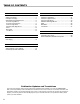
Table of Contents Introduction Bills of Materials Safety Procedures..................................................... 3 Principles of Design.................................................. 5 Specifications and Dimensions................................. 8 Aluminum High Mount.............................................. 21 Aluminum High Pressure......................................... 22 Cast Iron High Mount............................................... 23 Stainless Steel High Mount..............
Safety Procedures NOTICE This manual provides warnings and procedures that are intended to inform the owner and/or operator of the hazards present when using the Liquid Controls Meter on LPGas and other products. The reading of these warnings and the avoidance of such hazards is strictly in the hands of the owner-operators of the equipment. Neglect of that responsibility is not within the control of the manufacturer of the meter.
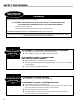
Safety Procedures Safely Evacuate Be Prepared Piping System ! WARNING Before disassembly of any meter or accessory component: ALL INTERNAL PRESSURES MUST BE RELIEVED AND ALL LIQUID DRAINED FROM THE SYSTEM IN ACCORDANCE WITH ALL APPLICABLE PROCEDURES. -Pressure must be 0 (zero) psi. -Close all liquid and vapor lines between the meter and liquid source. For Safety Rules Regarding LPG, refer to NFPA Pamphlet 58 and local authorities.
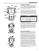
Introduction Principles of Design Liquid Controls mechanical air and vapor eliminators remove air and vapor from metering systems. Removing the air and vapor from a metering system increases the accuracy of the meter by allowing only liquid to pass through the meter for measurement. At installation, LC mechanical air and vapor eliminators are piped to a storage tank to provide a pathway and a receptacle where the evacuated air and vapor can be deposited.
Introduction Principles of Design Air Check and Differential Valves Air check and differential valves are spring loaded valves on the outlet side of the meter. Most Liquid Controls meter systems with an air eliminator also have an air check or a differential valve. Air eliminators and air check (or differential) valves work in conjunction to stop the flow of product through the meter until the air is eliminated from the system.
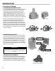
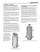
Introduction Principles of Design Dual Head Bulk Plant Air Eliminators By employing two air eliminators, a high mount air eliminator and a low mount air eliminator, dual head bulk plant air eliminators save the metering system from shocks incurred by recurring small slugs of air (or vapor) and prevent large slugs of air from passing by the air eliminator and through the meter system. Each time a standard air eliminator removes a small slug of air, it closes the downstream differential valve.
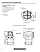
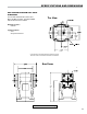
Specifications and Dimensions Aluminum High Mount Air & Vapor Eliminators For use with aluminum M-5, M-7, M-10, M-15, M-25, M-30, M-40, M-60 and M-80 meters. Typically installed with aluminum F7, F15, and F30 strainers. Top View Working Pressure • 150 PSI Typical Products • Refined Fuels Consult the factory when certified engineering drawings are required. Dimensions shown are not suitable for construction or modifications. 1" NPT - 2 Places Side Views 8.
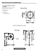
Specifications and Dimensions High Pressure Aluminum Air & Vapor Eliminators For use with aluminum MA-4, MA-5, and MA-7 and MA-15 meters. Typically installed with the aluminum FA7 strainer. Top View Working Pressure • 350 PSI Typical Products • LPG • Anhydrous Ammonia Consult the factory when certified engineering drawings are required. Dimensions shown are not suitable for construction or modifications.
Specifications and Dimensions Cast Iron High Mount Air & Vapor Eliminators For use with cast iron M-7 meters. Can be installed with cast iron F7 strainers. Bottom View Working Pressure • 150 PSI Typical Products • Chlorinated Solvents Consult the factory when certified engineering drawings are required. Dimensions shown are not suitable for construction or modifications.
Specifications and Dimensions Stainless Steel High Mount Air & Vapor Eliminators For use with stainless steel M-5 class 8 and M-7 class 8 meters. Installed with stainless steel F7 class 8 strainers. Bottom View Working Pressure • 150 PSI Typical Products • Acidic Solutions Consult the factory when certified engineering drawings are required. Dimensions shown are not suitable for construction or modifications.
Specifications and Dimensions Steel Air & Vapor Eliminators For use with MS, MSAA, and MSA series steel case meters. Installed with FS, FSAA, and FSA steel series strainers. Top View Working Pressure Three models available • 150 PSI, 275 PSI and 300 PSI Typical Products • Refined Fuels • Light Hydrocarbons Consult the factory when certified engineering drawings are required. Dimensions shown are not suitable for construction or modifications.
Specifications and Dimensions Steel Bulk Plant Air Eliminators For use with aluminum M or MS series meters. Working Pressure • 150 PSI Choices of 3, 4, 6 and 8 inch ANSI flanged connections. Offered in single head, dual head, and single head with optical sensor models to provide high venting capacity for metering into storage systems. Typical Products • Refined Fuels Optical Sensor - Power Input: Available with ANSI flanges only. Flanges might not match aluminum meters. • +10 to +28VDC • 0.
Specifications and Dimensions Steel Low Mount Air Eliminators For use with filter/separators. Top View Working Pressure • 150 PSI Typical Products • Aviation Fuels Consult the factory when certified engineering drawings are required. Dimensions shown are not suitable for construction or modifications.
Field Piping ! WARNING Relieving Internal Pressure All internal pressure must be relieved to zero pressure before disassembly or inspection of the strainer, vapor eliminator, any valves in the system, the packing gland, and the front or rear covers. Serious injury or death from fire or explosion could result in performing maintenance on an improperly depressurized and evacuated system. Relieving Internal Pressure Procedure for LPG and NH3 Meters 1. Close the belly valve of the supply tank. 2.
Field Piping Piping Configurations & Connections Piping configurations for Liquid Controls mechanical air and vapor eliminators are determined by two factors, the presence or absence of a valve in the meter system and the presence or absence of bypass ports and a limited bleed valve plate in the mechanical air eliminator assembly. If the meter system has an air check or differential valve, the air or vapor eliminator and the valve must be piped together.
Field Piping Piping Guidelines • Pipe with as little restriction as possible. By minimizing restrictions, the air or vapor eliminator will work as efficiently as possible. • ¾" (or larger) pipe/hose is recommend to vent air or vapor to the storage tank. • ½" pipe/hose is recommended for piping to an air check or differential valve (⅜" is acceptable). • If using hose, choose a type that will not collapse in on itself (heater hose, hydraulic hose, etc.).
Maintenance ! WARNING Relieving Internal Pressure All internal pressure must be relieved to zero pressure before disassembly or inspection of the strainer, vapor eliminator, any valves in the system, the packing gland, and the front or rear covers. Serious injury or death from fire or explosion could result in performing maintenance on an improperly depressurized and evacuated system. Relieving Internal Pressure Procedure for LPG and NH3 Meters 1. Close the belly valve of the supply tank. 2.
Maintenance To Replace the Reed Strips & Float Assemblies 1. Remove the 4 screws and washers at the base of the air eliminator. Pull the air eliminator off the strainer. 2. Remove the baffle plate and the baffle cup (aluminum air eliminators only) from the housing. If the air eliminator has a lock nut and a bushing on the bottom of the guide post, remove them. 3.
Bills of Materials Aluminum High Mount Air and Vapor Eliminators A8180 Series Part numbers in regular font Item numbers in italics Part numbers are for the A8197 standard air eliminator only Piping with Valve To Air Check/Differential Valve To Supply/Storage Tank 20 * 4 cover gaskets (0434) are required on air eliminators with kalrez seals Piping with no Valve To Supply/Storage Tank
Bills of Materials Aluminum High Pressure Air and Vapor Eliminators A8340A Series Part numbers are for the A8197 standard air eliminator only * 4 cover gaskets (0434) are required on air eliminators with kalrez seals Part numbers in regular font Item numbers in italics Piping with Valve To Air Check/Differential Valve Piping with no Valve To Supply/Storage Tank To Supply/Storage Tank 21
Bills of Materials Cast Iron High Mount Air and Vapor Eliminators A8976 Series Part numbers are for the A8977 standard air eliminator only * 4 cover gaskets (0434) are required on air eliminators with kalrez seals Part numbers in regular font Item numbers in italics Piping with Valve Piping with no Valve To Supply/Storage Tank To Supply/Storage Tank To Air Check/Differential Valve 22
Bills of Materials Stainless Steel High Mount Air Eliminators A8985 Series Part numbers are for the A8985 standard air eliminator only * 4 cover gaskets (0434) are required on air eliminators with kalrez seals Part numbers in regular font Item numbers in italics Piping with Valve To Air Check/Differential Valve Piping with no Valve To Supply/Storage Tank To Supply/Storage Tank 23
Bills of Materials Steel Air and Vapor Eliminators with Strainer Cover A8930 Series Part numbers are for the A8935 standard air eliminator only * 4 cover gaskets (0434) are required on air eliminators with kalrez seals Part numbers in regular font Item numbers in italics Piping with Valve Piping with no Valve To Supply/Storage Tank To Supply/Storage Tank To Air Check/Differential Valve 24
Bills of Materials Bulk Plant Air Eliminators A8950 Series A8170 A8950 Part numbers in regular font Item numbers in italics Part numbers are for the A8170 standard air eliminator only Piping with Valve Dual Head Piping To Supply/Storage Tank To Air Check/Differential Valve 25
Bills of Materials Low Mount Air Eliminators A8175 Series Part numbers are for the A8175 standard air eliminator only Piping with Valve Part numbers in regular font Item numbers in italics Piping with no Valve To Supply/Storage Tank To Supply/Storage Tank To Air Check/Differential Valve 26
Bills of Materials Single Head Bulk Plant Air Eliminator with Optical Sensor Piping with no Valve A89501 - 3" A89541 - 4" A89561 - 6" To Supply/Storage Tank A8170 BOM on page 25 Condulet Box w/ Optical Sensor 81947 Optical Sensor (sensor only) To configure the Single Head Bulk Plant Air Eliminator with Optical Sensor to MultiLoad: Wiring to LectroCount LCR-II or LCR 600 1.
Customer Service Contacting the Factory Before you contact the factory, note the model number and serial number of the component. The serial number directs us to a file containg all information on material specifications and test data applying to your specific component. When ordering parts, the Liquid Controls Group technical manual should be consulted for the proper part numbers. Always include the model number and serial number when ordering parts.
Customer Service Liquid Controls Return Material Authorization Requests When returning Liquid Controls products for repair, warranty evaluation or calibration, please follow these directions. 1. Remove all residue from the Liquid Controls component(s) to be returned. Make sure the grooves and corners around or inside seals and crevices are cleaned. This is particularly important if the component was in contact with hazardous materials. See Warning and Handling Procedure printed below. 2.
105 Albrecht Drive Lake Bluff, IL 60044-2242 1.800.458.5262 • 847.295.1050 Fax: 847.295.1057 www.lcmeter.com © 2005 Liquid Controls Pub. No.