Set-Up & Operation Manual LectroCount® LCR® Electronic Registers (with SR210 software) E2650/E2651 Series Enclosure (Class I, Division 1) Operation: EM100-21 www.lcmeter.
Table of Contents Recalibration/Proving w/o a Lap Pad ................. Single Point Recalibration/Proving ........ Basic Operation w/o a Lap Pad ......................... Delivery & Selections Menu .................. RUN Position ......................................... STOP Position ....................................... PRINT Position ...................................... SHIFT PRINT Position .......................... LCR Menu Flow Charts ......................................
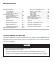
Truck Delivery System Truck Delivery System ! WARNING Power, input and output (I/O) wiring must be in accordance with the area classification for which it is used (Class I, Div 1). For NorthAmerica, installations must be per the U. S. National Electrical Code, NFPA 70, or the Canadian Electrical Code in order to maint ain Class I, Division 1 ratings. This may require using connections or other adaptations in accordance with the requirements of the authority having jurisdiction.
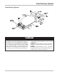
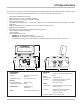
LCR System Components Communication and Programming Devices Pump & Print Lap Pad Hand Held Computer 4 Laptop Computer
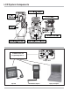
LCR Specifications The LectroCount LCR is a microprocessor based electronic register that offers the same advanced operation as previous LectroCount models but with additional benefits. The LectroCount LCR features include: • • • • • • • • • • • Full Weights & Measures Approvals Class I, Division 1, Group C, D safety approvals. NEMA 4X enclosure, Weights & Measures sealable Five conduit connections Operation with most flowmeters.
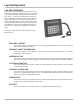
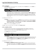
Lap Pad Operation LAP PAD OVERVIEW This section of the manual provides instructions for the initial set-up, calibration and operation of your LCR Electronic Register using the Liquid Controls Lap Pad dat a entry device. This section should first be scanned to become familiar with the components of the system, the layout and format of the document, the basic menu (screens) and data entry required. This section should then be carefully followed as the system is being set up and calibrated.
Lap Pad Operation NAVIGATING TOP-LEVEL MENUS When the LCR is powered up with a Lap Pad att ached, the Lap Pad will briefly display a copyright message for two seconds followed by the initial top-level menu. DELIVERY & PRESET Press Enter or Scroll with ARROW keys. Press the L key to navigate to the next top-level menu. Continue pressing the L key to scroll through the rest of the top-level menus (as seen below). Press the K key to navigate in the opposite direction.
Lap Pad Operation SECONDARY DATA SCREENS Each of the top-level menus has a secondary level consisting of one or more screens. Each screen is divided into one or more fields where data may be entered or information displayed. Access to data entry is dependent on the following: DATA FIELD TYPE: Some fields are for display only and dat a entry is not necessary (e.g. RATE). DIAGNOSTICS and FLOW PASSWORD PROTECTION: The LCR has a user-definable password that allows the system to be locked.
Lap Pad Calibration & Set-Up BEFORE GETTING STARTED • Make sure that the Lap Pad or other dat a entry device is connected to the LCR register as described in the LCR Installation Manual. • When proving the LCR system, follow the pre-test and inspection procedures established by Weights & Measures authorities. The primary indicating and recording element on a vehicle-mounted LCR is the 6-digit liquid cryst al display.
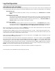
Lap Pad Calibration & Set-Up STEP 2: SECURITY Press the M1 Key to access a top-level menu. Press L to scroll to the SECURITY menu. Press ENTER to gain access to the secondary menu. Security - Screen 1 USER KEY SECURITY^ 0001 UNLOCKED USER KEY (Password) Use this field to enter the owner/office password. To enter a password, press ENTER to drop into the data entry field. Enter a p assword using up to 10 alphanumeric characters. Press ENTER.
Lap Pad Calibration & Set-Up STEP 3: GENERAL SETUP CONTINUED Press L and the cursor will move to: TIME HH:MM:SS This field is used to set the LCR internal clock. The time, like the date, is updated by the LCR and printed on the delivery ticket s. Press ENTER and the cursor will drop to the bottom line. Enter the current hour, minutes, and seconds. Use military time (e.g. press 13:01:15 for 1:01:15 PM). HINT: To synchronize the clock to the second, pressENTER when the appropriate second is reached.
Lap Pad Calibration & Set-Up STEP 3: GENERAL SETUP CONTINUED NO-FLOW TIMER CONTINUED Press ENTER and the cursor will drop to the bottom line. Enter the desired NO-FLOW TIMER value inseconds. Press ENTER and the cursor will move to the top line. Press L and the cursor will move to: General Setup - Screen 3 PRESET^ PRESET TYPE^ GROSS CLEAR PULSE OUTPUT EDGE^ RISING PRESET^ Available preset options include NET, BOTH, GROSS, and NONE. Selecting NONE will disable presetting.
Lap Pad Calibration & Set-up STEP 3: GENERAL SETUP CONTINUED General Setup - Screen 4 HDR^ TICKET HEADER LINE 1 HDR^ This field is used to select the line number of the ticket header that will be edited in the following field. Press ENTER and the cursor will drop to the bottom line. Use the LK keys to scroll through the numbers from 1 to 12. When the desired choice is displayed, press the ENTER key and the cursor will move to the top line.
Lap Pad Calibration & Set-up STEP 4: SYSTEM CALIBRATION From the top-level menu, use L to scroll to SYSTEM CALIBRATION. Press ENTER and the cursor will move to: System Calibration - Screen 1 METER ID TICKET? PRINTER 1234567890 YES EPSON NewFontB METER ID This number allows you to uniquely identify an LCR/Meter combination. If the LCR isart p of a multiplemeter system, it is import ant that this number be unique. It is recommended that the meter serial number be entered here.
Lap Pad Calibration & Set-up STEP 4: SYSTEM CALIBRATION CONTINUED DECIMAL^ This field allows you to choose between whole units, tenths and hundred ths of a unit. Press ENTER and the cursor will drop to the bottom line. Use L to scroll between WHOLE, TENTHS, and HUNDR. When the desired choice is displayed press ENTER and the cursor will move to the top line.
Lap Pad Calibration & Set-up STEP 4: SYSTEM CALIBRATION CONTINUED T UNIT^ This field allows you to choose the temperature units - Degrees Fahrenheit or Degrees Celsius. Press ENTER and the cursor will drop to the bottom line. Use L to scroll between the two choices, DEG. F and DEG. C. When the desired choice is displayed, press ENTER and the cursor will move to the top line. Press L and the cursor will move to: RTD SLP Factory calibration setting only.
Lap Pad Calibration & Set-up STEP 5: PRODUCT & SHIFT INFORMATION Press ENTER and the cursor will move to: Product & Shift - Screen 1 #^ PROD TYPE 1 DISTILLATE SHIFT START 7/01/2002 1:44:00 DLVRY 22 #^ (Product Number) This field is used to select one of four possible product types/calibrations. Press ENTER and the cursor will drop to the bottom line. UseL to scroll through the numbers 1-4.
Lap Pad Calibration & Set-up STEP 5: PRODUCT & SHIFT INFORMATION CONTINUED UNITS^ From this field, a unit of measure is selected. ChooseGALLONS, LITRES, CUBIC M, LBS (pounds), KGS (kilograms), BARRELS, or OTHER. Press L and the cursor will move to: Product & Shift - Screen 3 #^ GROSS TOTAL 1 6193.8 NET TOTAL 0.0 UNITS GALLONS #^ (Product Number) This field is used to select one of four possible product types/calibrations.At least one calibration must be set up in the LCR to allow deliveries.
Lap Pad Calibration & Set-up STEP 6: PRODUCT CALIBRATION Press M1 to return to the top-level menu. Press i to scroll to PRODUCT CALIBRATION. There are four product calibrations that can be set up in the LCR. The products are calibrated one at a time.
Lap Pad Calibration & Set-up STEP 6: PRODUCT CALIBRATION CONTINUED COMPENSATION TYPE^ CONTINUED Scroll through the choices: Linear F, Linear C, API Table 24, API Table 54, API Table 6B, API Table 54B, API Table 54C, API Table 54D, NH3 or NONE. If "NONE" is selected, deliveries will be in gross quantities only. Net Quantities will read " 0" on the screen. Refer to the Compensation Types and Parameters table (Appendix A) when choosing the type of compensation to be used.
Lap Pad Calibration & Set-up STEP 6: PRODUCT CALIBRATION CONTINUED PRESET The Gross Preset amount is entered here. When this amount is reached the valve outputs are turned off. REMAINING The number of units remaining to be delivered on the current GROSS DELIVERY preset is displayed. UNITS^ Choose the units of measure to be displayed. The choices are GALLONS, LITRES, CUBIC M, LBS (pounds), KGS (kilograms), BARRELS, or OTHER. Use the hi keys to scroll through the choices. Press ENTER to make a selection.
Lap Pad Calibration & Set-up STEP 6: PRODUCT CALIBRATION CONTINUED AUX MULT This field is used to convert the quantity delivered, (e.g.GALLONS, LITRES) to an alternate volume or mass unit such as CUBIC METERS, LBS, etc. The user must furnish an applicable conversion factor. If AUX MULT is set to 0, it will not print on the delivery ticket. Example:To convert GALLONS to LBS, AUX MULT is calculated as follows: AUX MULT= (SpGr) x (8.345 Ibs/gal) (Where SpGr is the specific gravity.
Lap Pad Calibration & Set-up STEP 6: PRODUCT CALIBRATION CONTINUED Product Calibration - Screen 8 PROVER QTY UNITS^ PT^ 0.000 GALLONS 1 PT^ %ERROR 0.000 LINEAR^ SETUP This field is used to calibrate the meter/register at up to 10 dif ferent flow rates for each product type/ calibration. PROVER QTY This field needs to contain the exact volume in the prover tank tested at actual flow rate. When an entry is made, the actual %ERROR (delivery) against the base number will be recalculated automatically.
Lap Pad Calibration & Set-up MULTI-POINT CALIBRATION Multi-point calibration allows a flowmeter to be used over a wide range of flow rates without experiencing a loss in measurement accuracy dueA to the shape of the meter curve (usually at low flow rates). After determining the inaccuracy of the meter at a variety of flow rates and inputting that information into the LCR multi-point calibration table, accuracy corrections are then continuously made by the LCR based on the measured flow rate.
Lap Pad Calibration & Set-up MULTI-POINT CALIBRATION CONTINUED Product Calibration - Screen 3 #^ PULSE/UNIT 1 2222.000000 Step 5: PROVER QTY 0.000 UNITS GALLONS Refill the prover at the same flow rate as S tep 4 to verify that the meter remains within tolerance limits.
Lap Pad Calibration & Set-up MULTI-POINT CALIBRATION CONTINUED Step 5: Set the LINEAR^ field to APPLIED and enter it. This puts the linearizing algorithm into effect. The LCR will re-sort the multi-point table and display the point s in descending order by RATE. Do not be alarmed if the data changes in a givenPT^. If the error messageADJACENT POINTS OUT OF 0.
Lap Pad Basic Operation PRESET DELIVERY WITH A LAP PAD CONTINUED PRODUCT TYPE^ This field displays the product type previously selected in CALIBRATION. Press L to advance to: Delivery & Preset - Screen 2 NET COUNT GROSS COUNT 0.0 0.0 UNITS GALLONS GROSS COUNT This field displays a running tot al of the gross number of unit s for the current delivery . DISPLA Y ONLY. NET COUNT This field displays a running total of the net number of units for the current delivery. DISPLAY ONLY.
Lap Pad Basic Operation PRESET DELIVERY WITH A LAP PAD CONTINUED PRESET The PRESET amount can be entered here. A preset of GROSS or BOTH must have been selected in GENERAL SETUP. REMAINING This field displays the number of units remaining for the current delivery. DISPLAY ONLY. UNITS^ This field displays delivery units selected during CALIBRATION: GALLONS, LITRES, CUBIC METERS, LBS, KGS, BARRELS, and OTHER. Press L to advance to: Delivery & Preset - Screen 5 TAX/UNIT PRICE/UNIT 0.000 0.000 %TAX 0.
Diagnostics/Factory Calibration DIAGNOSTICS Most of the DIAGNOSTICS fields are for DISPLAY ONLY. They contain information that can be useful in troubleshooting. Diagnostics - Screen 1 DIAGNOSTIC MESSAGES^ TVC ACTIVE SUPPLY VOLTAGE 13.5 DIAGNOSTIC MESSAGES^ This field allows an operator to check pending diagnostic messages. PressENTER and the cursor will drop to the second line of the screen. PressL to scroll through the list of messages. The last message is "END OF LIST".
Diagnostics/Factory Calibration DIAGNOSTICS CONTINUED Diagnostics - Screen 4 PULSR FAULTS 0 PULSR FAULTS This field displays the number of quadrature pulser faults detected during the last delivery. DISPLAY ONLY. FACTORY CALIBRATION (ONLY ACCESSIBLE BY LC FACTORY PERSONNEL) Factory Calibration - Screen 1 R100.0 R128.6 RAW ADC -105.2 2884.7 796 R100.0 R128.6 RTD SLP 0.02475 RTD OFS 2.605 Used by qualified personnel to calibrate the temperature probe.
Recalibration/Proving without a Lap Pad SINGLE POINT RECALIBRATION/PROVING The addition of two control buttons on the LCR allows for single point recalibration or proving without the need of a Lap Pad or other data entry device. This calibration is limited to recalculating the k-Factor or single point recalibration for up to four dif ferent product types. These two buttons can be used to select dif ferent display values as well as enter product selections and preset values.
Recalibration/Proving without a Lap Pad SINGLE POINT RECALIBRATION/PROVING CONTINUED Press SELECT to advance to: Calibration - Screen 1, Product Number Prod 1 The current active Product Number is displayed. If a delivery is not active, the digit will be flashing, indicating that it can be changed. Press INCREASE to scroll through the options. These options are labeled Prod 1, Prod 2, Prod 3, and Prod 4. When the desired option has been chosen, pressSELECT.
Recalibration/Proving without a Lap Pad SINGLE POINT RECALIBRATION/PROVING CONTINUED CALIBRATION MENU Repeat the process above for each digit position until the value for each has been selected. When the least significant digit is entered, the k-Factor is recalculated and the display returns to Calibration - Screen 1. CALIBRATION - SCREEN 1 101.323 101.663 SELECT NOTE: If the new value entered is out of range for the LCR, "Error" will appear in the display .
Basic Operation without a Lap Pad DELIVERY & SELECTIONS MENU Once the LCR has been calibrated, a Lap Pad is not required for daily use of the register. There are two push buttons located on the LCR. These can be used to select different display values as well as enter product selections and preset values. SELECT is the the front button and the INCREASE is the rear button. Values displayed or entered depend on the position of the red Selector Switch.
Basic Operation without a Lap Pad DELIVERY & SELECTIONS MENU CONTINUED RUN Position (Flowrate/Temp.) Continued Press SELECT a second time (within 5 seconds) to display Temperature. Temperature Display 23.8 ºF This display shows the current temperature of fluid moving though the meter. Values will be shown in degrees Celsius or Fahrenheit, depending on the initial set-up selection. The display updates every ½ second. After 5 seconds, the display will return to Delivery Total. This screen is DISPLAY ONLY.
Basic Operation without a Lap Pad DELIVERY & SELECTIONS MENU CONTINUED PRINT Position (Product #/Totalizer) Turning the Selector Switch to the PRINT Position will cause the valve control outputs to turn off, closing the security valve. A ticket will be printed. Once the PRINT position has been entered, the delivery cannot be resumed. If tickets are required, the system will NOT allow another delivery to begin until the current ticket is printed.
Basic Operation without a Lap Pad DELIVERY & SELECTIONS MENU CONTINUED PRINT Position (Product #/Totalizer) Continued A shift ticket is printed when the Selector Switch is placed in theSHIFT PRINT Position for more than 2 seconds and a printer is loaded with paper and available to print the ticket. (NOTE: If the Selector Switch is turned to SHIFT PRINT and then out of SHIFT PRINT in less than 2 seconds, a Diagnostic/Calibration Information ticket is printed). Delivery Total is the initial display.
LCR Menu Flow Charts Selector Switch STOP Position of Selector Switch DELIVERY TOTAL 22345.6 SELECT PRODUCT NUMBER Prod 1 SELECT INCREASE PRODUCT NUMBER Prod 2 SELECT INCREASE PRODUCT NUMBER RUN Position of Selector Switch Prod 3 DELIVERY TOTAL SELECT 22345.6 INCREASE PRODUCT NUMBER SELECT Prod 4 FLOWRATE F 70.0 SELECT SELECT PRESET SELECT 00200.0 SELECT TEMPERATURE SELECT: Step through digits. INCREASE: Increment each position 0-9. 62.
LCR Menu Flow Charts PRINT Position of Selector Switch SHIFT Position of Selector Switch DELIVERY TOTAL 22345.6 DELIVERY TOTAL 22345.6 SELECT SELECT PRODUCT NUMBER Prod 1 PRODUCT NUMBER Prod 1 INCREASE (Scroll Through Products 1-4) INCREASE SELECT INCREASE PRODUCT NUMBER SELECT Prod 4 GROSS OR NET TOTALIZER SELECT GROSS OR NET TOTALIZER INCREASE SELECT L6789.0 L6789.
LCR Troubleshooting Guide To comply with Weights & Measures requirements, it is necessary to st art and stop each delivery with a fully p acked hose. Normally, this will be the case. However, there are times where the hose is not fully packed (e. g. after a preset delivery). As such, the hose must be packed and the register zeroed prior to making the next delivery. NOTE: This procedure will not work for an empty or dry hose.
LCR Troubleshooting Guide NOTE: Check for proper operating voltages before changing the circuit board. If the circuit board needs to be changed, be sure to remove all power to the LCR. 5. If an error occurs during a delivery , the message "* FAULT: PRINT DIAGNOSTICS TICKET*" will appear on the delivery ticket. The diagnostic ticket will contain an error message that can be useful in troubleshooting. Print a diagnostic ticket by moving the red Selector Switch to " SHIFT PRINT" for less than two seconds.
LCR Troubleshooting Guide PROBLEM PROBABLE CAUSE “Power Failure” Power to LCR interrupted appears on Lap during delivery. Pad or diagnostic ticket. Static discharge. SOLUTION 1. Check accessory power cable for damage. Ensure that the power, common and ground wires (11, 12 and 13) on power connector J6 are secure. J6 is located on the rear of the circuit board. 2. Turn on all truck accessories (headlamps, 2-way radio, heater, etc.).
LCR Troubleshooting Guide PROBLEM PROBABLE CAUSE Pulser shaft is not turning with Product flow does not register product flow. on Lap Pad or Pulser failure. LCR display SOLUTION 1. Manually spin the pulser shaft and monitor the LCR display. 2. If the LCR display counter increments, this may indicate a mechanical problem. Contact your local Liquid Controls Service Center or the Liquid Controls Service Department for assistance. 3.
LCR Troubleshooting Guide PROBLEM PROBABLE CAUSE SOLUTION Valve will not open. Solenoids are inactive or inoperative. 1. Insert a delivery ticket into the Epson printer and start a delivery. Foreign debris in system. 2. Move the selector switch from RUN to STOP and back to RUN. Listen for an audible clicking sound from the solenoids. 3.
Appendix A - Compensation Types & Parameters The table below shows the supported methods of calculating the Volume Correction Factor (VCF). The method is independently select able for each product in Product Calibration. The t able below shows the valid temperature ranges for each table. The hold temperature, Thold, is the temperature that VCF is held at for temperatures < Thold and > Tmin. This is done to allow compensation in very cold environments where further extrapolation of equations is not allowed.
Appendix B - Operation Using VT 100 Compatible Terminal If the LCR is operated using a VT 100 compatible terminal (instead of the LC Lap Pad), refer to the following chart for the terminal keystrokes that correspond to the Lap Pad keystrokes. VT 100 communication parameters that must be observed include: • • • • • Baud Rate (9600) Data Bits (8) Parity (None) Stop Bits (1) Flow Control (None).
Appendix C - Error Messages The LCR was designed to perform diagnostic analysis of problems as they occur. If an error should occur, one of the following messages may be displayed on the Lap Pad or printed on a Diagnostic Ticket (see troubleshooting section). The list below explains the error message and any possible corrective action. The LCR was designed to handle most foreseeable problems on it s own.
Appendix C - Error Messages DIAGNOSTIC MESSAGE LIST If an error occurs during a delivery, the message "*FAULT: PRINT DIAGNOSTICS TICKET*" will appear on the delivery ticket. The appropriate message below is then printed on the diagnostic ticket if an error has occurred. A diagnostic ticket is printed by loading a ticket into the printer and then moving the Selector Switch to the SHIFT PRINT position for less than two seconds.
Appendix C - Error Messages DIAGNOSTIC MESSAGE LIST CONTINUED DELIVERY END REQST This message appears when a PRINT command has been sent to the LCR system to terminate a delivery. PRINT can be activated from the Selector Switch, Lap Pad, or aTerminal. This is not an error condition POWER FAIL ERROR This message appears when a delivery was ended due to a loss of input volt age. Check the power supply and wiring to the LCR. Check the in-line fuse. See the troubleshooting section.
Appendix C - Error Messages DIAGNOSTIC MESSAGE LIST CONTINUED NET PRESET ACTIVE This message appears when a NET PRESET is active. The PRESET type must be set to NET or BOTH and a desired amount entered in the NET PRESET field. This is not an error condition. GROSS PRESET STOP This message appears when the GROSS PRESET amount has been reached. This is not an error condition. NET PRESET STOP This message appears when theNET PRESET amount has been reached. This is not an error condition.
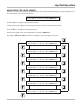
Appendix D - Lap Pad Menu Flow Charts GENERAL START UP LectroCount LCR SR210v1.00 (c) Copyright Liquid Controls, Inc. 2002 Displays for 2 Seconds DELIVERY & PRESET Press Enter or Scroll with ARROW keys. See DELIVERY & SETUP Menu PRODUCT & SHIFT INFORMATION Press Enter or Scroll with ARROW keys. See PRODUCT & SHIFT Menu GENERAL SETUP Press Enter or Scroll with ARROW keys. See GENERAL SETUP Menu SYSTEM CALIBRATION Press Enter or Scroll with ARROW keys.
Appendix D - Lap Pad Menu Flow Charts DELIVERY & PRESET MENU DELIVERY & PRESET Press Enter or Scroll with ARROW keys. M1 ENTER #^ 1 CODE PRODUCT NAME Depending on the position of the CURSOR, the ARROW Keys will do one of the following: • Scroll Forward one position • Scroll Backward one position • Jump to the first position on the next screen • Jump to the last position on the previous screen, (as depicted below). PROD TYPE^ M# M1 Cursor GROSS COUNT 0.0 NET COUNT 0.
Appendix D - Lap Pad Menu Flow Charts PRODUCT & SHIFT PRODUCT & SHIFT INFORMATION Press Enter or Scroll with ARROW keys. M1 ENTER #^ 1 PROD TYPE^ SHIFT START 01/01/02 00:00:00 DLVRY 0 M1 M# #^ 1 SHIFT GROSS 0.0 SHIFT NET 0.0 UNITS^ GALLONS M# #^ 1 M1 GROSS TOTAL 0.0 NET TOTAL 0.
Appendix D - Lap Pad Menu Flow Charts GENERAL SETUP GENERAL SETUP Press Enter or Scroll with ARROW keys.
Appendix D - Lap Pad Menu Flow Charts SYSTEM CALIBRATION SYSTEM CALIBRATION Press Enter or Scroll with ARROW keys. M1 ENTER METER ID TICKET? NO PRINTER^ EPSON NewFontB M# UNITS^ GALLONS M1 RATE BASE^ PER MINUTE DECIMAL^ TENTHS RESIDUAL^ TRUNCATE M# TEMP 25.00 M1 OFFSET 0.00 T UNIT^ DEG. F RTD SLP 0.02478 RTD OFS 2.
Appendix D - Lap Pad Menu Flow Charts PRODUCT CALIBRATION PRODUCT CALIBRATION Press Enter or Scroll with ARROW keys. M1 ENTER #^ 1 CODE PRODUCT NAME PROD TYPE^ M# M1 COMPENSATION TYPE^ NONE COMP PARAM ---------- BASE TEMP --------- M# #^ 1 M1 PULSES/UNIT 0.000000 PROVER QTY ---------- UNITS^ GALLONS M# M1 GROSS QTY 0.0 PRESET 0.0 REMAINING --------- UNITS^ GALLONS M# M1 GROSS QTY 0.0 NET QTY 0.0 UNITS^ GALLONS TEMP 25.0 M# M1 S1 CLOSE 0. 0 AUX MULT 0.000 AUX QTY 0.
Appendix D - Lap Pad Menu Flow Charts DIAGNOSTICS DIAGNOSTICS Press Enter or Scroll with ARROW keys. M1 ENTER DIAGNOSTICS MESSAGES END OF LIST SUPPLY VOLTAGE 12.7 M# M1 SOFTWARE SR210v1.00 LANGUAGE SL200v1.04 TICKET ST200v1.05 M# M1 GROSS COUNT 0.0 RATE 0.0 UNITS^ GALLONS RATE BASE^ PER MINUTE M# M1 PULSER FAULTS 0 M# SECURITY DIAGNOSTICS Press Enter or Scroll with ARROW keys. M1 ENTER USER KEY SECURITY^ LOCKED FACTORY R100.0 -87.2 R128.6 2902.9 RAW ADC 921 RTD SLP 0.
Appendix E - Weights & Measures Prover Guide This guide has been created to clearly convey the method for proving a meter system equipped with a LectroCount LCR electronic register without the use of a Lap Pad or external data entry device. This guide will only cover the software features of the LCR in the calibration/prover mode. NOTE: The following method provides a means to check the overall meter accuracy as well as adjust the meter's "k-Factor".
Appendix E - Weights & Measures Prover Guide k-Factor Adjustment Example: Presume that the LCR register displayed "101.235" Units and the prover volume was determined to be "100.593" units at the end of step 9. ("Units" represents the units of measure as designated on the front cover of the LCR.) When INCREASE is pressed in Step 9 above, the left most digit of the LCR register will be flashing on and of f, indicating that it can be changed. To change this value, press INCREASE to scroll through 0-9.
A Unit of IDEX Corporation 105 Albrecht Drive Lake Bluff, IL 60044-2242 1.800.458.5262 • 847.295.1050 Fax: 847.295.1057 www.lcmeter.com © 2007 Liquid Controls Pub. No.