
Install Manual

20
Wire ConnectionTables
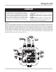
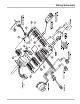
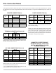
This appendix provides a tabular description of the wiring connections made to each LCR-II terminal block. It should
be referenced in the event wiring inadvertently mis-routed in the field, or for general troubleshooting in the event of a
problem.
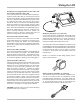
NOTE: Jumper J10 on LCR-II circuit board must be set
for RS-232 communication protocol.
* For a standard RS-232 terminal (other than the Lap
Pad), the black wire is connected to J3-47.
NOTE: Jumper J10 on LCR circuit board must be set for
RS-485 communication protocol.
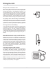
PRINTER CONNECTION (J1)
LAP PAD CONNECTION RS-232 (J3)
ODOMETER, PRESET/PRODUCT
SELECTOR SWITCH, START/STOP
SWITCH, AND INTERNAL PULSER
CONNECTIONS (J8)
TERMINAL CONNECTION RS-485 (J2)
*On free-end of cable, cut off foil shield and drain wire,
then insulate by taping.
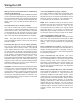
NOTE: The LCR-II Power cable kit includes a fuse holder
and 5 Amp fuse to protect the system in the event of a
short circuit in the cable. Liquid Controls recommends
that this fuse be used in all installations not having a
fused accessory block to protect the truck in the event of
cable faults. A 5 Amp fuse is required.
POWER CONNECTION (J6)
Connector/
Pin
Signal Wire Color Route To:
J6-13 Earth Drain/Green Wire No Connection*
12 GND Black DC Ground
11
+12V In
(or +24V In)
Red
+12VDC (or +24VDC)
(accessory truck circuit)
J1-30 GND Printer, Pin 7
29 CTS Printer, Pin 20
28 RXD Printer, Pin 2
27 TXD Printer, Pin 3
26 RTS Printer, Pin 6
Orange
Wire Color
Connector/
Pin
Signal Route To:
Cable #81513
Black
Blue
Yellow
Brown
Cable
#81572
Cable
#81513
J2-25 485-B Black Viloet Terminal
24 485+A Red Red Terminal
Route To:
Wire Color
Connector/
Pin
Signal
J3-51 GND Ground, Pin 5
50 CTS RTS Terminal, Pin 4
49 RXD TXD Terminal, Pin 3
48 TXD RXD Terminal, Pin 2
47 RTS CTS Terminal, Pin 8
46 +Vo Lap Pad +12, Pin 8
Red
Route To:
Wire Color
Cable #81513
White
Green
Gray
Violet
*
Connector/
Pin
Signal
Connector/
Pin
Signal Wire Color Route To:
J8-38 GND Black
Preset switch or Remote
Start/Stop switch
37 GND Black
Internal pulser and
Odometer ground
36 In1 Violet
Odometer pulser or
remote Start/Stop switch
35 In2 Gray Preset switch
34 In3 Green Int. Pulser "B"
33 In4 White Int. Pulser "A"
32 +5V Out Red Int. Pulser "+"
31 +Vo Odometer +12V