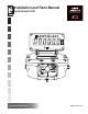
Installation and Parts Manual LectroCount LCR Installation: EM100-20 www.lcmeter.
Table of Contents Description Page Number Sytstem Overview ........................................................................ 3 Installation Overview .................................................................... 4 Specifications ............................................................................... 5 Regulatory Specifications ............................................................ 6 Parts Requirements .....................................................................
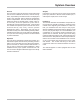
Sytstem Overview Outputs Information from the LCR can be output via an RS-232 printer port, RS-485 or RS-232 communication port, a scaled pulse output,and a counter output. General The LectroCount LCR is an electronic meter register that can be used to calibrate a flow meter, control a security valve, output delivery information via an LCD display and printer, and, optionally, perform electronic temperature volume compensation.
Installation Overview Electrical check for Truck Installations Before beginning the installation, make sure that the truck electrical system meets the minimum requirements to correctly power the LCR. The truck system should produce at least 12.6 VDC to reliably power the LCR and the valve control solenoids. Truck systems that do not meet this requirement need to be serviced to ensure that the LCR will be reliably powered. The LCR computer will power down if the voltage drops below 9 VDC.
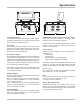
Specifications Power Requirements +9 to 28 Volts DC @ less than 3 Amps for entire register including solenoid valves. The system can operate with either a positive or negative ground. Up/Down/Reset pulse to Remote electronic counter Open drain transistor capable of sinking 1 Amp. Maximum open circuit voltage is 28 VDC. Pulses are active low and are approximately 10 μsec in duration. The LCD counter is reset by turning on both outputs for 0.01 second.
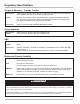
Regulatory Specifications Weights & Measures - Custody Transfer United States NTEP Certificate of Conformance #86-022. Complies with requirements in NIST handbooks 44 and NCWM Publication 24 for use with any approved meter. Canada Measurements Canada Notice of Approval #AV-2342. Complies with Weights & Measures Acts, Regulations, Specifications, Bulletins, and Rulings/Interpretations including specifications SVM-1 and SVM-2 for use with any approved meter.
Parts Requirements Liquid Controls Supplied Components LCR register, and LC-supplied options including; printer, Lap Pad, control valve or solenoid, ETVC kit, glandless pulse output device (POD), odometer kit, preset switch, remote START/STOP switch, communication protocol selector switch (RS232/485), power cable, and printer/ Lap Pad cable.
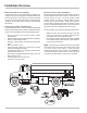
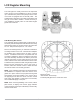
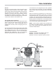
LCR Register Mounting The LCR register is usually mounted on the liquid flow meter, though for fixed installations it can be mounted up to 1000 wire feet (304.0 meters) away from the meter if the meter is equipped with an external pulser. The actual distance depends on the pulser specifications and the type of wire used to install it. Contact the factory if your installation requires pulser or RTD cable lengths greater than 1000 feet.
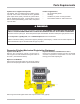
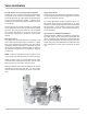
Valve Installation If the solenoid is not energized by the LCR, upstream high pressure liquid is directed to the valve diaphragm and the valve closes, preventing product from being delivered. General The LCR can provide security valve and preset control capabilities via the Solenoid 1 and 2 outputs. Singlestage and two-stage solenoid actuated valves and threeway solenoids can be controlled. Valves should be installed in accordance with accepted industry practice and Weights & Measures regulations.
Valve Installation Fuel Oil Trucks Preset/Security Valve Installation Installing an LCR on a refined fuel truck typically requires the removal of the system’s mechanical valve. Those trucks equipped with air check valves should retain them as part of the air elimination system. However, an air check valve will not perform well as a preset/security valve on fuel trucks. Single-Stage Valves Single-stage solenoids should be connected to the SOL2 control.
Wiring the LCR ! WARNING Power, input and output (I/O) wiring must be in accordance with the area classification for which it is used (Class I, Div 2). For North America, installations must be per the U. S. National Electrical Code, NFPA 70, or the Canadian Electrical Code in order to maintain Class I, Division 2 ratings. This may require using connections or other adaptations in accordance with the requirements of the authority having jurisdiction.
Wiring the LCR Wiring of Valve Solenoids to LCR When wiring valve solenoids to the LCR, the wires may have to be spliced in order to reach the appropriate terminal strip location. Use stranded 18 GA wire. It is recommended that red wire be used for the main connections, though black can be used as a substitute. Green 18 GA stranded wire should be used for the solenoid case ground. Leave a small amount of excess wire to allow for future servicing of the junction box wiring.
Wiring the LCR Installing factory-supplied printer Power cable, LCR Power Cable, and printer data cable Your LCR includes an electrical black-sheathed10conductor printer data cable for connecting the LCR at the rear of the vehicle to the printer located in the vehicle cab, and a separate gray-sheathed 3-wire power cable for connecting the LCR to the accessory circuit in the vehicle cab. For your convenience, the cables have been factory pre-wired to the LCR, and are ready for routing to the vehicle cab.
Wiring the LCR Wiring Customer-Furnished Remote START/Stop Switch to LCR (Optional) A user-supplied momentary remote START/STOP Switch can be connected to terminal block J8, Pins 36 and 38 in lieu of the odometer pulser. For programming instructions to activate the user supplied remote START/STOP Switch, refer to the LCR Set-up Manual (Bulletin No. 500050). connecting handheld or lap top computer The LCR is capable of interfacing to a handheld or lap top computer.
Wiring the LCR Installing a Valve with 110VAC Solenoids This step applies only to configurations that will be using a two-stage valve with 110VAC solenoids. 6. Run the cables through the conduit or cable gland between the solenoids and relays and then connect the conduit to the solenoid valve and the relays. Using a two-stage valve with solenoids operating on 110VAC requires the use of two relays.
Guidelines for Environmental Sealing The LCR contains a printed circuit board with sensitive electronic components that can be damaged by the presence of moisture. Conformal coating on the board and a moisture-absorbing desiccant inside the enclosure mitigates the problem of moisture corroding the LCR board.
System Startup After the LCR has been installed, check to make sure that it will power up correctly. The back light on the LCR display should go on when the truck’s ignition key is turned to the “ON” or the “accessory” position. At this point, you need to attach a compatible data terminal to the LCR to initialize system values, set the clock, enter ticket headers, calibrate the meter, etc. The user can use a Liquid Controls Lap Pad, handheld computer, or lap top computer.
Wiring Schematic 18
Wiring Schematic 19
Wire ConnectionTables This appendix provides a tabular description of the wiring connections made to each LCR-II terminal block. It should be referenced in the event wiring inadvertently mis-routed in the field, or for general troubleshooting in the event of a problem.
Wire Connection Tables AUXILIARY OUTPUTS (J12) LIQUID CONTROLS POD (J8) Connector/ Pin Signal Wire Color Route To: Connector/ Pin J8-38 - - - 37 GND Black Pulser Signal GND 36 - - - 35 - - - 34 In 3 Green Channel B Output 33 In 4 White Channel A Output 32 - - - 31 +Vo Red +V Input SINGLE CHANNEL PULSER (J8) Connector/ Pin Signal Wire Color Signal Wire Color Route To: J12-45 +Vo N/A 44 Out 1 (Aux. 1) N/A Pump or Aux. Control 43 Out 2 (Aux.
Illustrated Parts Breakdown 22
Illustrated Parts Breakdown 23
A Unit of IDEX Corporation 105 Albrecht Drive Lake Bluff, IL 60044-2242 1.800.458.5262 • 847.295.1050 Fax: 847.295.1057 www.lcmeter.com © 2007 Liquid Controls Pub. No.