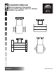
Installation Manual Electromagnetic Flowmeters Models HMS501, HMS600, HMS1000, HMS2400, HMS2500, and HMS5000 Installation www.lcmeter.
Table of Contents Description Page Number Introduction .................................................................................. 2-3 General ........................................................................... 3 Applications ..................................................................... 3 Basic Components .......................................................... 3 Safety Legend ................................................................. 3 Unpacking .............................
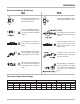
Introduction General Unpacking This manual contains information concerning the application, installation, and operation of the HMS501, HMS500, HMS1000, HMS2410, MS2500, and HMS5000 full bore flow meters. Keep a copy of this manual with the flow meter for future reference. Always inspect the instrument for damage from shipping upon receipt. File a damage claim with the carrier if damage is discovered. Transportation and Handling Do not lift the instrument from the carton by the converter head.
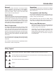
Installation Flow Direction Before installing the sensor, confirm the direction of the liquid flow in the piping. The sign of the flow rate is positive, when the flow direction is from - to + as printed on the nameplate on the sensor body. If flow direction is reversed after the installation, it is sufficient to reverse the sign of the KA coefficient in the converter (refer to converter installation manual). Lifting Meters with Eyebolts Recommended hoisting procedure for sensors with lifting eyebolts.
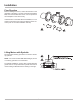
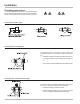
Installation Sensor Installation Guidelines NO YES For vertical installations with descending flow direction contact the manufacturer. For vertical installations, use ascending flow conditions, only. Avoid the installation of the sensor in a long unsupported pipe line. Always provide adequate support. For installations on long runs of pipe use anti-vibration joints, as shown Avoid operation of the instrument with the pipe partially empty.
Installation Grounding Instructions For correct operation of the meter, it is essential that the sensor and the liquid are at the same electrical potential. Always connect the sensor and the converter to ground.
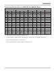
Installation Torque Specifications (Nm) for HMS1000 and HMS2500 Meters Operating Pressure (PSI) 140 Liner PTFE 260 Ebon. PTFE Ebon. 350 PP PTFE 600 Ebon. PTFE 1000 Ebon. Ebon. N.
A Unit of IDEX Corporation 105 Albrecht Drive Lake Bluff, IL 60044-2242 1.800.458.5262 • 847.295.1050 Fax: 847.295.1057 www.lcmeter.com © 2005 Liquid Controls Pub. No.