
Owner's manual

7
Installation
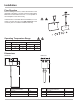
Model 3700 (installation in pressurized systems)
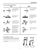
Step 1
Step 2
Weld a 1" pipe to the
pipeline.
NOTE: Verify “X”
dimension (Step 2).
Step 3
Screw the 1" jacket to
the valve.
NOTE: The O-Ring in
the jacket must be
placed underside (near
valve).
Step 4
Step 5
Step 6
Open the valve.
Screw the sensor up to
the “Z” dimension.
Verify the alignment.
Tighten the block nut
maintaining alignment.
Insert the sensor with
valve closed.
Tighten the lock nut with
wrench.
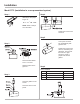
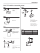
Length Z = L - S -
1
/
8
D
X
MAX
= 5.5"
Size Nominal Diameter Range L
Size 1 3" up to 20" 19"
Size 2 3" up to 40" 24.5"
Size 3 3" up to 80" 34.5"