Installation Manual Electromagnetic Flowmeters Models HMS3700 & HMS3770 Insertion Sensors Installation www.lcmeter.
Table of Contents Description Page Number Introduction .................................................................................. 2-3 General ........................................................................... 3 Applications ..................................................................... 3 Basic Components .......................................................... 3 Safety Legend ................................................................. 3 Unpacking .............................
Introduction General Unpacking This manual contains information concerning the application, installation, and operation of the HMS3700 and HMS3770 insertion flow meters. Keep a copy of this manual with the flow meter for future reference. Always inspect the instrument for damage from shipping upon receipt. File a damage claim with the carrier if damage is discovered. Transportation and Handling Applications Do not lift the instrument from the carton by the converter head.
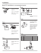
Installation Flow Direction Before installing the sensor, confirm the direction of the liquid flow in the piping. The sign of the flow rate is positive when the flow direction is from - to + as printed on the nameplate on the sensor body. If flow direction is reversed after the installation, it is sufficient to reverse the sign of the KA coefficient in the converter (refer to converter installation manual). Operating Temperature Range PTFE Wetted Parts Liquid Temp. Min. Max.
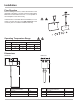
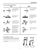
Installation Sensor Installation Guidelines NO YES For vertical installations with descending flow direction contact the manufacturer. For vertical installations, use ascending flow conditions only. Avoid operation of the system with the pipe partially empty. During normal operation of the instrument, the pipe must be completely full of liquid, or completely empty. Avoid installation of this instrument near bends in the piping or accessories such as valves.
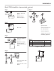
Installation Model 3770 (installation in a non-pressurized system) Step 1 Step 4 Cut the jacket (1" diameter) to the proper length “Z”. Z = L - S - 1/8 D - 1.26" NOTE: Refer to Step 6 for L dimension. Tighten the lock nut with a wrench. Step 5 Line up the connector box longitudinally with pipe line axis. Step 2 Tighten the lock nut with wrench, maintaining the alignment. Ensure that the lock nut is tight enough to create a proper seal with the gasket. Recommended dimension of 1" thread.
Installation Model 3700 (installation in pressurized systems) Step 1 Step 5 Weld a 1" pipe to the pipeline. NOTE: Verify “X” dimension (Step 2). Step 2 Open the valve. XMAX = 5.5" Screw the sensor up to the “Z” dimension. Verify the alignment. Tighten the block nut maintaining alignment. Step 3 Screw the 1" jacket to the valve. Step 6 NOTE: The O-Ring in the jacket must be placed underside (near valve). Size Nominal Diameter Range L Size 1 3" up to 20" 19" Size 2 3" up to 40" 24.
A Unit of IDEX Corporation 105 Albrecht Drive Lake Bluff, IL 60044-2242 1.800.458.5262 • 847.295.1050 Fax: 847.295.1057 www.lcmeter.com © 2005 Liquid Controls Pub. No.