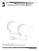
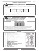
HML4-F1 Converter LCMag Electromagnetic Flowmeters Installation & Operation Release number: 4F1_EN_LC_R1_3_9X The last three digits of file name identify the software version which the manual refers to; it is visualized at the instrument start up, or by specific function on DIAGNOSTIC menu.
HML4-F1 INDEX q q q q q q q q q q q q q q q q q Introduction _______________________________________________ pag.3 Safety informations ___________________________________ pag.3 § Safety conventions __________________________________________ pag.4 Technical characteristics ____________________________________ pag.5 § Electrical characteristics ______________________________________ pag.5 § Environmental use conditions _________________________________ pag.
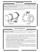
HML4-F1 INTRODUCTION These operating instructions and description of device functions are provided as part of the scope of supply. They could be modified without prior notice. The improper use, possible tampering of the instrument or parts of it and substitutions of any components not original, renders the warranty automatically void.
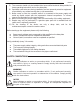
HML4-F1 5) The converter should only be installed after have verified technical data provided in these operating instructions and on the data plate. 6) Specialists must take care during installation and use personal protective equipment as provided by any related security plan or risk assessment. 7) Never mount or wire the converter while it is connected to the power supply and avoid any liquid contact with the instrument’s internal components. To connect remove the terminals from the terminal block.
HML4-F1 TECHNICAL CHARACTERISTICS ELECTRICAL CHARACTERISTICS Converter classification: class I, IP 67, installation category (overvoltage) II, rated pollution degree 2. Power supply versions LLV Power supply voltage 18-30V Max power 10W q q q Voltage variations must not exceed ±10% of the nominal one.
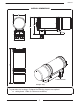
HML4-F1 OVERALL DIMENSIONS 107 89 65 177 53 CABLE GLAND Weight: 2kg TORQUES To guarantee the housing’s IP degree the following torques are required: q cable glands: 1.
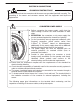
HML4-F1 ELECTRICAL CONNECTIONS GROUNDING INSTRUCTIONS ALWAYS ensure that the converter and the sensor are grounded (earthed) correctly. The grounding of the sensor and converter ensures that the equipment and liquid are equipotential. CONVERTER POWER SUPPLY - q q q q + q Before connecting the power supply, verify that the mains voltage is within the limits indicated on data plate. q ATTENTION: the converters on dc power supply line are not protected against the inversions of polarity.
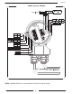
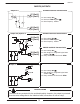
HML4-F1 INPUT/OUTPUT CABLES + MAIN POWER OUTPUT 4-20 -+ "A" RS485 PROFIBUS "B" RS485 PROFIBUS JACK FOR IF2X 2 20 21 2 5 23 24 2 26 + INPUT 2 C. OUTPUT 3 - INPUT 2 E. OUTPUT 3 6 14 15 1 9 17 18 1 C. OUTPUT 1 E. OUTPUT 1 C. OUTPUT 2 E. OUTPUT 2 + INPUT 3 C. OUTPUT 4 - INPUT 3 E. OUTPUT 4 + INPUT 1 - INPUT 1 IN / OUT CABLES NOTE: shielded cables are recommended for inputs and outputs wiring.
HML4-F1 SENSOR CABLES Dangers voltage: - 60V max - 250V max commutation coils circuit 13 12 1 1 1 2 3 4 COIL 1 COIL 2 COMMON ELECTRODE 2 ELECTRODE 1 CABLES FROM SENSOR 9
HML4-F1 INPUTS/OUTPUTS Output 1-2 OUTPUTS technical characteristics + 17 (Out 1) 21 (Out 2) q Max voltage 30V q Max load: 100mA @24V q Max frequency: 1250Hz. , - 18 (Out 1) 22 (Out 2) Output 3-4/Input 2-3 OUTPUTS technical characteristics + 19 (Out 3) 23 (Out 4) 47K q Max voltage 30V q Max load: 100mA @24V q Max frequency: 1250Hz.
HML4-F1 OPTIONAL EXPANSION MODULES Output 4-20mA q q q q mA Power supply 18-30V Max load resistive to the output: 800Ω with 24V of power supply Minimum load recommended 500Ω Setting time: 5ms 14 + I ATTENTION: The power supply of 420mA is the same of that of entire instruments, therefore is not insulated from it.
HML4-F1 DIGITAL INPUT Input electric wiring Speed rate 10 K 25 (+) 20 Hz 50 Hz 60 Hz 80 Hz 150 Hz 5/33 VDC (ON) 0/1.5 VDC (OFF) Tmin 110 ms 45 ms 40 ms 30 ms 15 ms 26 (-) ATTENTION: where not specified the time T must be to Tmin The functions refer to the inputs could be substantially divided in three groups: 1. 2. 3.
HML4-F1 INPUT OPERATION STAGE (GENERIC FUNCTIONS) Auto-calibration Tmin 1 sec. = Autozero AUTOCALIB. OFF Necessary conditions for enable the function 3-40 V POS. 5.5 ENABLED POS. 5.7-8-9 batch functions assign to input 1-2-3 (optional) DISABLED (op 0-1.5 V POS. 6.1-2-3-4 batch functions assign to output 1-23-4 DISABLED T Reset totalizers Necessary conditions for enable the function BLOCK RESET 3-40 V POS. 5.1-2 ENABLED at least one 0-1.
OPERATION STAGE ON INPUT 1 OR 2 OR 3 (BATCH FUNCTION) Start batch from remote input Necessary conditions for enable the function INPUT 3-40 V 0-1.5 V Closing valve OUTPUT Opening valve BATCH POS. 5.7 ENABLE or POS. 5.8 or 5.9 on batch POS. 6.1-4 on end batch Start batch from consent (remote) Necessary conditions for enable the function INPUT 3-40 V 0-1.5 V Closing valve Opening valve OUTPUT Opening valve BATCH Start batch from remote input with autobatch enabled 0-1.
HML4-F1 OPERATION STAGE ON INPUT 1 and 2 or 1 and 3 (BATCH FUNCTION) Start batch on remote input 1 stop from output selection formula 00 o 01 from remote input 2 INPUT 1 Start 3-40 V 0-1.5 V BATCH FORMULA 00 BATCH FORMULA 01 3-40 V BATCH FORMULA 01 BATCH FORMULA 00 POS. 6.1 or 6.3 on END BATCH OUTPUT Closing valve Opening valve POS. 5.7 ENABLED POS. 5.8 or/and 5.
HML4-F1 FLAGS AND LED INTERPRETATION FLAGS FLAG ! C S FLAGS INTERPRETATION DESCRIPTION Alarm max/min activated - Interruption coils circuit - Signal error - Empty pipe Calibration running Simulation Pulse output saturation (reduce TIME PULSE) LED 20 21 22 14 15 16 17 18 19 23 24 25 26 LED INTERPRETATION PERMANENT LIGHT: initialization FLASHING LIGHT ( 1 sec.): normal function FLASHING LIGHT (<1 SEC.
HML4-F1 FLOW RATE VISUALIZATION The instrument can show a 5 digit character display for flow rate units; this mean the maximum flow rate value that can be represented on the display is 99999 (no matter the positioning of the decimal point). The minimum is 0.0025. The representable measure unit depends from sensor flow rate and diameter; the permitted units are those, set the instrument full scale value, allow to be represented with a numerical field which the maximum value do not exceed 99999.
HML4-F1 ACCESS TO THE CONFIGURATION MENU The converter configuration menu can be accessed ONLY using ISOCON interface (cable and software needed). ISOCON INTERFACE Isocon is a Windows® software that allows to set all the converter functions and personalize the menu (IF2X is required), see suitable manual for details.
HML4-F1 VISUALIZATION PAGES Flow rate value * Three vertical bars % full scale Flow direction +/reg.regolazione Date/time or alarm See: anomalies codes and flags interpretation Direct/reverse totalizer C=Calibration S=Simulation Sampling rate Flow speed The three vertical bars represent the filters behaviors: first bar, “F”, is the FAST filter, second bar, “S”, is the “SLOW” filter and the third bar represents the variation of the new measure samples respect to the averaged value.
HML4-F1 QUICK START MENU The user has immediate access to the Quick Start menu when the converter is powered up by pressing the key Enter. If access to the quick start menu does not occur, then it has been disabled through the function 8.
HML4-F1 EXAMPLE: modifying the full scale value from 4dm³/s to 5dm³/s, from the “Quick start menu” Enter in the Quick start menu Access to the function “Fs1” Push repeatedly Change the value Confirm the new value Main page 21
HML4-F1 EXAMPLE: modifying the full scale value from 4dm³/s to 5dm³/s, from the “Main Menu” (quick start menu enabled) Enter in the Quick start menu Access to the Main Menu X 5 TIMES Confirm the keycode Access to the Scale menu Access to the function “Fs1” Change the value Confirm the new value Push repeatedly Main page 22
HML4-F1 PROGRAMMING FUNCTIONS (functions with access code < 3, those with symbol “*” see next section) Functions in grey colour are visualized on display only with other active functions or with optional modules 1.1 1.2 1.3 1.4 Insert the Nominal Diameter of the sensor (0-3000mm) Calibration data of sensor visualized on sensor label Sensor model: enter the first two characters of the sensor serial number Factory parameters 1.5 1.6* 1.7* 1.
HML4-F1 6.1* 6.2* 6.3* 6.4* 6.5* Output 1 functions Output 2 functions Output 2 functions Output 4 functions Choice of the function and the range of current output n.1 7.1 7.2 7.3 7.4 Choice of the communication protocol for the IF2 device Address value of the converter Speed of the RS485 output (possible choices: 4800, 9600, 19200, 38400 bps) Instrument answer delay 8.1 8.2 8.3 8.4 8.5* 8.
HML4-F1 FUNCTIONS DESCRIPTION (description of the functions with access code< 3) Identification of the function (not visualized on display) MENU 1.SENSOR (POS. 1.1) Nominal diameter of sensor [ND= XXXX] Converter request Menu visualized on the converter (from 1 to 11) Synthetic description of the function The following pages give a description of the most important functions and how they can be changed or enabled/disabled by the user. MENU 1 - SENSOR (POS. 1.6) Electrodes cleaning [E.
HML4-F1 Where fsmax is the maximum full scale value corresponding to the sensor, equal to a 10 m/sec liquid speed. The units of measure are shown as appear on the display. The British and American units are diversified by using capital and small characters.
HML4-F1 MENU 3 – MEASURE (POS. 3.2) Measure filter [M. filter=s XXX.X] This section of the manual is extremely important because the right settings of filters allow to get a proper meter reaction according to the flow rate behaviour. WORKING PRINCIPLE There are two filters: MFSLN (Measure Filter Slow LeNght): available via ETP and through the display, in menu 3. Measure, function “M. filter” The M.
HML4-F1 The following diagrams show the response of the instrument for a flow rate variation from 0 to 100% of full scale set using different settings of filters. 60 Both filters to zero (batching setup): the measure quickly follows the flow rate behaviour 50 FLOW RATE (%) 40 30 20 IN >>>> 10 FLOW RATE FILTERS MFSLN: 0,0s MFFLN: 0,0s O UT >>>> MEASURE 0 0 2 4 6 8 10 12 14 16 18 20 22 TIME (Sec) 1,0sec. 1,0sec.
HML4-F1 (POS. 3.3) Measure filter AC enable [AC Line fil.=ON/OFF] This function allow to filter electrical noise on the liquid coming from the main frequency. (POS. 3.6) Automatic scale change enable [Autorange=ON/OFF] Enables the automatic change of scale. The meter may have two different working ranges in order to suit to the variable process conditions. In order to get the best results out of this function it is important range N.2 is bigger than N.1.
HML4-F1 MENU 6 - OUTPUTS (POS. 6.1-4) Function corresponding to on/off output 1-2-3-4 [OUT1=XXXXXX] Choice of the function corresponding to digital Output 1.
HML4-F1 MENU 8 - DISPLAY (POS. 8.5-6) Totalizer 1-2 reset [T1/2 reset] These functions are activated pressing the key Enter during the function visualization. When "EXECUTE?" is required, press Esc/Del/Canc to proceed; or any other key to delete the operation. MENU 9 - BATCH Visualized only with batch active (output on batch and/or pos. 5.8 enable or pos. 5.9 on batch) (POS. 9.1) Number of batch samples [N.SAMPLES=XXX] Number of batch cycles to be done to define the value of compensation.
HML4-F1 MENU 10 - DIAGNOSTIC (POS. 10.1) Meter calibration [CALIBRATION] Enable the calibration of the meter. The activation of this function happens pressing the key Enter during the function visualization. Will be visualized the following question: "EXECUTE?" press the key Esc/Del/Canc to proceed. Press any other key to delete the operation (POS. 10.2) Autotest function enable [SELF TEST] Meter autotest function.
HML4-F1 BATCH FUNCTION ENABLE BATCH Enable one of the following functions to enable and program the batch on the converter: q POS. 5.7-8-9: START/STOP batch from input q POS. 6.
HML4-F1 START STOP BATCH START: it is possible activate the start of batch in two different way: 1. from remote input: assigning the functions of start/stop batch to the input 1 (POS. 5.7) or input 2-3 (POS. 5.8-9) and using the input/s like visualized from page 14. from keyboard: pressing of the key N.B.: the start of batch from keyboard is always on the descent front (release of the key) and is not available with the function of batch consent (POS. 9.7) 2.
HML4-F1 ALARMS Causes and actions to be taken ANOMALIES Messages NO ALARMS ACTION TO TAKE All works regularly ----- MAX ALARM The flow rate is higher than the maximum threshold set Check the maximum flow rate threshold set and the process conditions MIN ALARM The flow rate is lower than the minimum threshold set Check the minimum flow rate threshold set and the process conditions FLOW RATE >FS The flow rate is higher than the full scale value set on the instrument Check the full scale value se
CONFORMITY DECLARATION it declares under the own responsibility that the product: Converter model: HML 110 Sensors model: HMS 501 – HMS 600 – HMS 1000 – HMS 2410 – HMS 2500 – HMS 3770 – HMS 3800 – HMS 5000 to which this declaration refers, is in compliance with the following Harmonized European Norms: § EN 61010-1:2010 § EN 61326-1:2006 and therefore answering to essential requirement of CE directives: § 2006/95/CE (Low voltage directive – LVD) § 2004/108/CE (Electromagnetic compatibility Directive – EMC)
Liquid Controls 105 Albrecht Drive Lake Bluff, IL 60044 (847) 295-1050 Liquid Controls Europe/SAMPI Via Amerigo Vespucci 1 55011 Altopascio (Lucca), Italy +39 0583 24751 IDEX Fluid and Metering Pvt. Ltd. Survey No. 256, Alindra Savli GIDC, Manjusar Dist.