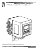
HML210 Converter LCMag Electromagnetic Flowmeters Installation & Operation Release number: 210_EN_LC_R8_3_9X – The last three digits of file name identify the software version which the manual refers to; it is visualized at the instrument start up, or by specific function on DIAGNOSTIC menu.
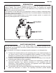
HML 210 INTRODUCTION These operating instructions and description of device functions are provided as part of the scope of supply. They could be modified without prior notice. The improper use, possible tampering of the instrument or parts of it and substitutions of any components not original, renders the warranty automatically void.
HML 210 information about the converter. If you are unclear on anything in these Operating Instructions, you must call the service. 5) The converter should only be installed after have verified technical data provided in these operating instructions and on the data plate. 6) Specialists must take care during installation and use personal protective equipment as provided by any related security plan or risk assessment.
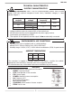
HML 210 TECHNICAL CHARACTERISTICS ELECTRIC CHARACTERISTICS Instrument classification: class I, IP67 for compact/separate version, IP54 for panel version (IP65 with optional transparent frontal cover), installation category II, rated pollution degree 2. Power supply versions HV LV LLV q q q q Power supply voltage 100-240V~ 18-45V~ 18-45V 10-35V Power supply frequency Pmax 44-66Hz 25VA // 20W Voltage variations must not exceed ±10% of the nominal one.
HML 210 OVERALL DIMENSIONS COMPACT VERSION 146 SEPARATE VERSION 170 146 138 170 230 138 146 146 25 138 138 WEIGHT Compact 3kg 2.5kg INOX AISI 304 Alluminum Separate 3.5kg 3kg PANEL VERSION Weight: 0.5kg 0 137. 160.0 1 45. 72.0 80.0 67.0 0 1 44 .0 IP65, TRASPARENT FRONTAL COVER (OPTIONAL) TORQUES To guarantee the compact/separate housing’s IP degree the following torques are required: q cover screws: 1.
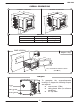
HML 210 ELECTRICAL CONNECTIONS GROUNDING INSTRUCTIONS ALWAYS ensure that the converter and the sensor are grounded (earthed) correctly. The grounding of the sensor and converter ensures that the equipment and liquid are equipotential. CONVERTER POWER SUPPLY Panel version Compact/separate version M3 L (+) M3 N (-) L (+) N (-) q Before connecting the power supply, verify that the mains voltage is within the limits q q q q q q q indicated on data plate.
HML 210 COMPACT/SEPARATE VERSION M1 TERMINAL BLOCK Power supply IF2 socket LOCK 1 Signalling LED: see display flags and led warning interpretation section 2 3 4 5 6 7 8 9 10 11 12 13 14 15 16 17 18 19 20 21 22 23 24 25 26 M3 27 28 29 30 31 32 M1 M2 Dip switch, when the switch is ON, there is NO more access to the programming functions Dangerous voltage on block 12-13: - 60V Max - 250V Max on commutation coils PANEL VERSION M1 TERMINAL BLOCK Dangerous voltage on block positions 12-13: - 60V M
HML 210 CONVERTER TO SENSOR ELECTRICAL CONNECTIONS SEPARATE VERSION TERMINAL BLOCK M1 M1 1 2 E1 E2 3 C 4 SH 11 SH 12 B1 E1 ELECTRODES E2 C SH INPUT + - RS485 B A 4-20mA + - 1 2 3 4 5 6 7 8 9 10 13 B2 ALL SENSORS 11 12 13 14 15 16 17 18 19 20 SH Sudden movements of the electrodes cable, can cause noise on measure. Max cables length: 20m. B1 COILS B2 SH + 24V C E OUT1 C E OUT2 SENSOR WITH PREAMPLIFIER ALL SENSORS WITH PREAMPLIFER Max cable length: 500m 9 10 (preamp.
HML 210 OPTIONAL MODULES OPTIONAL MODULES (NO RELÈ MODULES) q ME200: 2 programmable on/off outputs + 1 on/off input q ME201: 1 programmable on/off output + 1 high frequency output + 1 on/off input q ME202: 1 4-20mA output + 2 programmable on/off output + 1 on/off input q ME203: 1 RS232 port + 2 programmable on/off outputs + 1 on/off input q ME204: 1 RS232 port + 2 programmable on/off outputs + 1 4-20mA output + 1 on/off input q q ME220, ME221, ME222: data logger, see the related manual Protocol
HML 210 LEGEND OPTIONAL RELÈ MODULES q q ME205: 2 relay outputs with 1 NO contact + 1 NC contact each, 2A 60V~, 60W/125VA 2 relay outputs with 1 NO ME207: contact + 1 NC contact each, 2A 250V~, 60W/125VA Teminal block on compact/separate version q SH: Cable shield, electrically connected to ground and to the casing q C: Relay – common q NC: Normally closed contact q NO: Normally open contact Teminal block on panel version OUT 3 OUT 4 OUT 3 NO NC C OUT 4 C NO NC NC NO C NC NO C 26 25 24
HML 210 INPUTS/OUTPUTS DIGITAL INPUT External power supply Internal power supply +24 10k 5 (+) 15 5 10k 3-40VDC (ON) 0-1.5VDC (OFF) 6 6 (-) 0 20 The functions referring to the inputs could be divided in three groups: 1) 2) 3) only assignable functions to the input 1 functions that act directly on the inputs independently from the select input only assignable functions to the input 1 and only to the input 2 which interact between them For details see the following pages.
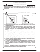
HML 210 OPERATION ON INPUT ON/OFF INPUT OPERATION STAGE (GENERIC FUNCTIONS) Auto-calibration Tmin 1 sec. = Auto zero AUTOCALIB. OFF Necessary conditions for enabling the function 3-40 V POS. 5.7 ENABLED (Autozero calibration external command) POS. 5.9 DISABLED (batch on input 1) 0-1.5 V POS. 5.10 DISABLED (batch functions assign to input 2 (optional) T Reset totalizers Necessary conditions for enabling the function BLOCK POS. 5.1 to 5.
HML 210 OPERATION STAGE ON INPUT 1 OR 2 (BATCH FUNCTION) Start batch from remote input Necessary conditions for enabling the function INPUT 3-40V 0-1.5V Closing valve POS. 5.9 or POS. 5.10 ENABLED on batch POS. 6.1 to 6.4 on end batch OUTPUT Opening valve q q BATCH Start batch from consent (remote) Necessary conditions for enabling the function INPUT 3-40V 0-1.5V Closing valve Opening valve OUTPUT Opening valve BATCH Start batch from remote input with autobatch enabled 5 Sec. <5 sec. 0-1.
HML 210 OPERATION STAGE ON INPUT 1 AND 2 (BATCH FUNCTION) Start batch on remote input 1 stop from output selection formula 00 o 01 from remote input 2 Necessary conditions for enabling the function Closing valve Opening valve Closing valve Opening valve BATCH FORMULA 00 BATCH FORMULA 01 3-40V BATCH FORMULA 01 BATCH FORMULA 00 q POS. 5.9 ENABLED q POS. 6.1 or 6.4 on BATCH q POS. 5.10 ENABLED function of formula selection 00/01 assigned to input 2 (optional) INPUT 2 0-1.
HML 210 OUTPUT WIRINGS Output on/off 1250Hz 16 (out1) 18 (out2) q q q q q 43V q 17 (out1) 19 (out2) q Opto-insulated output with collector and emitter terminals floating and freely connectable Maximum switching voltage: 40V Maximum switching current: 100mA Maximum saturation voltage between collector and emitter @100mA: 1.
HML 210 CONVERTER ACCESS FLAGS AND LED INTERPRETATION FLAGS FLAGS INTERPRETATION FLAG DESCRIPTION Alarm max/min activated - Interruption coils circuit ! - Segnal error - Empty pipe C Calibration running S Simulation Pulse output saturation (reduce TIME PULSE ) LED LOCK 1 2 3 4 5 6 7 8 9 10 M3 11 12 13 14 15 16 17 18 19 20 M1 LED INTERPRETATION PERMANENT LIGHT: initialization FLASHING LIGHT (1 sec.): normal function FLASHING LIGHT (<1 sec.
HML 210 KEYBOARD SHORT PRESSING (< 1 SECOND): Increases the numeric figure or the parameter selected by the cursor Returns to the previous subject on the menu Batch start/stop (when enabled) LONG PRESSING (> 1 SECOND): Decreases the numeric figure or the parameter selected by the cursor.
HML 210 START-UP VISUALIZATION PAGES The direct exposure of the converter to the solar rays, could damage the liquid crystal display. For the contrast set see pos. 8.3 Three vertical bars Flow rate value Flow direction +/reg.
HML 210 FLOW RATE VISUALIZATION The HML 210 can to show a 5 digit character display for flow rate units; this mean the maximum flow rate value that can be represented on the display is 99999 (no matter the positioning of the decimal point). The minimum is 0.0025. The representable measure unit depends from sensor flow rate and diameter; the permitted units are those, set the instrument full scale value, allow to be represented with a numerical field which the maximum value do not exceed 99999.
HML 210 ACCESS CODES Functions in the converter main menu are enabled by the access codes. The information of this manual is related to all the functions available with the L2 level. All the functions available through higher level are protected and reserved to the service. Description of the L2 access code (menu “11 Internal data” pos. 11.
HML 210 QUICK START MENU The user has immediate access to the Quick Start menu when the converter is powered up by pressing the key . If access to the quick start menu does not occur, then it has been disabled through the function 8.
HML 210 ACCESS TO THE CONFIGURATION MENU The converter configuration menu can be accessed in two different ways: 1) by ISOCON interface 2) by keyboard of converter ACCESS TO THE CONFIGURATION MENU BY ISOCON INTERFACE Isocon is a Windows® software that allows to set all the converter functions and personalize the menu (IF2X is required), see suitable manual for details ACCESS TO THE CONFIGURATION MENU BY THE KEYBOARD Functions can be accessed by the keyboard in two different ways: q The Quick start menu
HML 210 EXAMPLE: modifying the full scale value from 4dm³/s to 5dm³/s.
HML 210 EXAMPLE: modifying the full scale value from 4dm³/s to 5dm³/s.
HML 210 PROGRAMMING FUNCTIONS (functions with access code < 3, those with symbol “*” see the next section) Attention: The menu functions in grey colour are visualized on display only with other active functions or with optional modules 1.1 1.2 1.3 1.4 Insert sensor ND (0-3000mm) Sensor calibration data, visualized on sensor's label Type of sensor: Enter the first two characters of the sensor serial number Position for insertion sensors: 0=1/8DN, 1=1/2DN, 2=7/8DN 1.
HML 210 5.1* Total direct (positive) flow totalizers reset enable 5.2* Partial direct (positive) flow totalizers reset enable 5.3* Total reverse (negative) flow totalizers reset enable 5.4* Partial reverse (negative) flow totalizers reset enable 5.5 Reset totalizers of pulse from digital input (see page 13) 5.6 Totalizers counting lock command (see page 13) 5.7* Autozero calibration external command 5.8 Range change external command (see function 3.5) 5.
HML 210 9.1* 9.2 9.3 9.4 9.5 9.6 9.7 9.8 9.9 Date and time set Automatic data logger enable Interval time for the data logging function: 1, 2, 3, 6, 8, 12, 24, 48 hours Displaying of the data stored in the data logger Displaying of the last 64 alarms stored in the data logger Visualization function of minimum and maximum peak of flow rate Logged data cancel function Reset all alarm events Reset all minimum and maximum peak of flow rate stored 10.1* 10.2* 10.3* 10.
HML 210 FUNCTIONS DESCRIPTION (description of the functions with access code< 3) Identification of the function (not visualized on display) MENU 1-SENSOR (POS. 1.1) Nominal diameter of sensor [ND= XXXX] Converter request Menu visualized on the converter (from 1 to 11) Synthetic description of the function The following pages give a description of the most important functions and how they can be changed or enabled/disabled by the user MENU 1 - SENSOR (POS. 1.8) Electrodes cleaning [El.
HML 210 where fsmax is the maximum full scale value corresponding to the sensor, equal to a 10m/s liquid speed. The measure units are shown as appear on the display. The British and American units are diversified by using capital and small characters.
HML 210 (POS. 3.2) Measure filter [M. filter=s XXX.X] This section of the manual is extremely important because the right settings of filters allow to get a proper meter reaction according to the flow rate behaviour. WORKING PRINCIPLE There are two filters: MFSLN (Measure Filter Slow LeNght): available via ETP and through the display, in menu 3. Measure, function “M. filter” The M.
HML 210 The following diagrams show the response of the instrument for a flow rate variation from 0 to 100% of full scale set using different settings of filters. 60 Both filters to zero (batching setup): the measure quickly follows the flow rate behaviour 50 FLOW RATE (%) 40 30 20 10 0 IN >>>> FLOW RATE 0 2 4 6 FILTERS MFSLN: 0,0s MFFLN: 0,0s 8 10 O UT >>>> 12 TIME (Sec) MEASURE 14 16 1,0sec. 60 50 18 20 22 1,0sec.
HML 210 (POS. 3.5) Automatic scale change enable [Autorange=ON/OFF] Enables the automatic change of scale. The meter may have two different working ranges in order to suit to the variable process conditions. In order to get the best results out of this function it is important range N.2 (Fs2) if enabled is bigger than N.1 (Fs1). When the flow rate increases and reaches the 100% of the full scale 1, then the meter automatically switches to scale 2.
HML 210 MENU 5 - INPUTS (POS. 5.1-4) Reset totalizer enable [T/P+/-RESET=ON/OFF] When one of this function is enabled, the related totalizer may be reset through the on/off input. (POS. 5.7) “Autozero” calibration external command enable [Calibration=ON/OFF] When this function is active, applying a voltage on the on/off input terminals the meter performs a autozero calibration cycle. ATTENTION: If the voltage pulse is less than 1 sec.
HML 210 (POS. 6.5-6) Function and the range of current output n.1-2 [Out mA1-2=X÷XX+] The function associated to the signal current on output N.1-2. The current output N.1 is optional and it is mounted on the main board.
HML 210 (POS. 8.13-16) Total/partial totalizers reset [T/P/-/+ reset] Activates the reset of total and partial flow totalizer. These functions are activated by pressing the key during the visualization of the function itself. When "EXECUTE?" is required, press to proceed. Press any other key to delete the operation. MENU 9 - DATA LOGGER (POS. 9.1) Date and time set [· = dd/mm/yy hh:mm] Date and time set.
HML 210 The batch functions allow the user to set the converter to measure a defined volume of fluid and control outputs. An example is opening and closing a value after a predefined volume has passed the sensor. The user sets the volume and the control parameters by the converter through the follwing fuctions (Main menu function group 12 Batch) MENU 12 - BATCH Menu visualized only with batch active (output on batch and/or pos. 5.9 enable or 5.10 on batch) (POS. 12.1) Number of batch samples [N.
HML 210 BATCH FUNCTION CONFUGURATION ENABLE BATCH Select one of the following functions to enable and program the batch on the converter: q POS. 5.9-10: START/STOP batch from input q POS. 6.1-2: assign one of the functions ouputs one and/or two Some examples of operation of such functions are visualized from page 14.
HML 210 START STOP BATCH START: it is possible to activate the start of batch in two different ways: 1. 2. From remote input: assigning the functions of start/stop batch to the input 1 (pos. 5.9) or input 2 (pos. 5.10) and using the inputs like visualized from page 14. From keyboard: short pressing of the key N.B.: The start of batch from keyboard is always initiated on the release of the key. The function is not available with the batch consent (pos. 12.7) function enabled.
HML 210 ALARM MESSAGES CAUSES AND ACTIONS TO BE TAKEN Messages ANOMALIES ACTION TO TAKE NO ALARMS All works regularly MAX ALARM The flow rate is higher than the maximum threshold set Check the maximum flow rate threshold set and the process conditions MIN ALARM The flow rate is lower than the minimum threshold set Check the minimum flow rate threshold set and the process conditions FLOW RATE >FS The flow rate is higher than the full scale value set on the instrument Check the full scale value
HML 210 APPENDIX DISPLAY ROTATION PROCEDURE Fixing screw of board Pic.4 1 Pic.5 3 4 Pic.1 2 Unscrew the screw as indicated in pic. 1 q Take off the flat cable Pic.2 q q Rotate the display to the desired location, verify the correct set of the seal, the cleaning of the contact surfaces it set the display housing. q Place the fixing angles in the suitable positions (pic. 5) and screw down firmly until they make contact with the display housing.
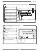
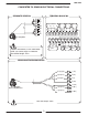
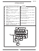
LCMag Meter Pulse Output to LectroCount Input J17 with Jumper 84040 840404 LC Part #71045 Terminal Block M1 IRF 530 1VR 216F 0A OI 10K J4 with Jumper 81920 813902 81547 1. Use a 10K Ω pull up resistor between terminals 15 and 16 on the LCMag Converter. 2. Install a jumper wire between teminals 17 and 20 to tie the collector to the ground. 3. Wire the FTE according to the schematic above. 4. In the OUTPUT menu of the LCMag flowmeter, set the OUT1+ to oneof the following: IMP+, IMP- or IMP+/5.
CONFORMITY DECLARATION it declares under the own responsibility that the product: Converter model: HML 210 Sensors model: HMS 501 – HMS 600 – HMS 1000 – HMS 2410 – HMS 2500 – HMS 3770 – HMS 3800 – HMS 5000 to which this declaration refers, is in compliance with the following Harmonized European Norms: § EN 61010-1:2010 § EN 61326-1:2006 and therefore answering to essential requirement of CE directives: § 2006/95/CE (Low voltage directive – LVD) § 2004/108/CE (Electromagnetic compatibility Directive – EMC)
Liquid Controls 105 Albrecht Drive Lake Bluff, IL 60044 (847) 295-1050 Liquid Controls Europe/SAMPI Via Amerigo Vespucci 1 55011 Altopascio (Lucca), Italy +39 0583 24751 IDEX Fluid and Metering Pvt. Ltd. Survey No. 256, Alindra Savli GIDC, Manjusar Dist.