
Installation Instruction Manual

14
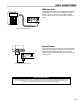
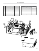
DATA CONECTIONS
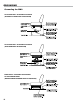
81920 LECTROCOUNT CPU BOARD
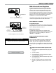
84040 LECTROCOUNT CPU BOARD
Data Cable
VIOLET
RED
VIOLET
RED
Move jumper to 485 position
If using protocol switch
move to down position
Move the red and violet wires
from 46 & 48 to 24 & 25,
respectively, on terminal block J2.
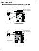
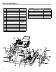
52 53 54 55 56
PRINTER SERIAL 485 TERMINAL
COUNTER
MH1
CTS RXD TXD RTS GNDGND 485+A485-B CTS RXD TXD RTS +VP
AUX OUTPUTS
PULSE INPUTS
AUX I/O
GND
GND
GND
IN 1
OUT1
OUT2
OUT3
TEMPERATURE PROBE
ASSY
84040
REV.
RTD+S
RTD-D1
RTE-S
RTD+D
OUT4
OUT5
IN 2
IN 3
IN 4
+5V OUT
+VP
+VP
PGND
OUT6
+VP
SOL
+VPPGNDOUT7
+VF
+VFIN5 OUT8GND
MH4
C1
J20
11 12 13
POWER
EARTH
GND
+12-24V
J6
J3J2J1
J7
J12
J15
P1
TP1
J5
J14
J18
J19
J10
J17
J11
J7
C2
MH5
MH3
MH2
A
B
24
25
Data Cable
VIOLET
RED
VIOLET
RED
Move the red and violet wires
from 46 & 48 to 24 & 25,
respectively, on terminal block J2.
The 84040 CPU board
automatically recognizes
RS-232 and RS-485
Wiring Lectrocount Registers to Communicate with the DMS