DMS Liquid Controls Group An IDEX Fluid & Metering Business Installation Operation: EM200-10
Table of Contents Introduction Bill of Materials Safety Procedures..................................................... 3 DMS System Overview ............................................ 4 DMS System Components ....................................... 5 Specifications ........................................................... 6 Dimensions............................................................... 7 Bill of Materials......................................................... 18 Exploded Views...........
Safety Procedures Be Prepared ! WARNING • Before using this product, read and understand the instructions. • All work must be performed by qualified personnel trained in the proper application, installation, and maintenance of equipment and/or systems in accordance with all applicable codes and ordinances.
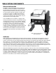
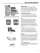
DMS System Components General Information The DMS is a data management system designed for fuel delivery vehicles. The DMS is a computer with a lap pad interface that mounts in the cab of a delivery vehicle. It interfaces with the LectroCount® LCR®, LCRII®, and LCR 600® electronic registers on single, dual, or triple meter systems. The DMS gathers data from the electronic registers, combines it with your unique customer and transaction data, and transfers it to your office PC and your accounting system.
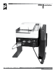
DMS System Overview Metering System Typically mounted to the back or side of a delivery vehicle, the metering system accurately measures, stops and starts the flow, and preserves the purity of the product. A Liquid Controls metering system can include the meter, a LectroCount electronic register, a strainer, an ETVC (temperature compensation) probe, an air eliminator, and a control valve.
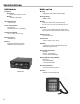
Specifications DMS Module DMS Lap Pad Enclosure Housing Dimensions • 6.875” W x 2.625” H x 7.25” L Material • Powder coated steel Operating Voltage • Lightweight, high impact, molded plastic Housing Rating • NEMA 3, IP54 Display • +9 to 30 VDC Power Consumption • 5A maximum • 60 watts (maximum, intermittent) Temperature Rating • -22° to 158°F (-30° to 70°C) • LCD, dot matrix, 240 x 64 pixels, backlit, 5.2” W, 1.
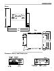
Dimensions Front Top Terminals, Ports, and Connections 7
Installation Installation Overview This manual assumes a meter system and an LCR-II Lectrocount register is installed on the truck. Only the physical and electrical installation of the DMS will be covered. Specific installation requirements will vary with the model of vehicle and the configuration of the existing meter system.
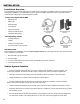
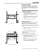
Mounting Mounting the DMS The DMS is shipped mounted to the support brackets. There are four B⁄zn" holes drilled into the base of the support brackets for mounting the DMS to the floor of the cab. Mounting bolts and washers must be provided by the installer. Before mounting the DMS in the truck cab, find a suitable place in the cab that takes into account the following considerations: • Leave space around front and rear panels for data/power connections and the USB flash memory device.
Grounding Grounding the DMS After the DMS is mounted, you must ensure that the DMS is properly grounded. Without a proper ground, the DMS is susceptible to damage in the event of static discharges and voltage spikes. To protect the DMS, LC ships each unit with a ground strap kit (82180). Each kit contains two ground straps. One strap is for grounding the support brackets to the chassis. The other strap grounds the seat to the chassis. If the truck has two seats, both seats must be grounded.
Grounding Grounding the DMS Ground the seat: Grounding the Truck Seat Static electricity can build up on truck seats and the drivers themselves, especially during cold, dry weather. Adjustable, shock-absorbing seats are especially vulnerable because they isolate the seat cushion from an electrical ground. If electrostatic discharge (ESD) occurs on or near the DMS, the truck’s electrical system, its components, and the DMS are all susceptible to damage.
Grounding Grounding the DMS Air Cushion Seat - Adjustable for Height (Bostrom 914 Series Seat or equivalent) Air Cushion Seat - Adjustable for Height (Dura-Form Seats or equivalent) Bench Seats - Adjustable for Distance to the Steering Wheel (Manufacturers Standard Seats or equivalent) 12
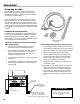
Data Conections DMS & LectroCount Registers Register Data Cable 40’ PN 81513040 Electronic Register 1 Connection Connecting the DMS and a LectroCount register(s) together for data communication requires some minor rewiring on the LectroCount 81920 CPU board. Two wires from the 40' data cable (PN 81513040) must be moved to different terminals. The connector at the other end of the data cable must be plugged into the specified DMS port.
Data Conections Data Cable Move the red and violet wires from 46 & 48 to 24 & 25, respectively, on terminal block J2. VIOLET RED RED VIOLET Wiring Lectrocount Registers to Communicate with the DMS Move jumper to 485 position If using protocol switch move to down position VIOLET RED Move the red and violet wires from 46 & 48 to 24 & 25, respectively, on terminal block J2.
Data Conections DMS Lap Pad The DMS lap pad connects to the DMS via the attached, coiled cable. The DB-9 connector plugs into the port labeled “Lap Pad” on the front of the DMS. Tighten the two captive screws on the connector to secure it in place. DMS Lap Pad Connection Epson Printer The printer data cable has a DB-25 connector that plugs into the back of the printer and a DB-9 connector which plugs into the “Printer Signal” port on the front panel of the DMS.
Power Connections Electronic Registration Power DMS 1. Pull the 10 pin, center terminal block off the back of the DMS. 2. Connect the red wire from the register’s power cable to pin 1 and the black wire from the register’s power cable to pin 2. Black To supply power to LectroCount register(s) through the DMS: Red The DMS can supply power to one, two, or three LectroCount registers. Drain Wire Register Power Cable 81512/84062 LectroCount Register Power Connection 4.
Power Installation Connecting Power to the DMS Before Powering Up the DMS Do not apply power to the DMS Module until the LectroCount Register has been rewired for RS-485 communication. Refer to page 13 for instructions on rewiring the LectroCount Register for RS-485 communictaion. Failure to rewire the LectroCount register prior ro applying power may result in damage to the DMS Module. The DMS power cable (Part No.
Bill of Materials Optional Items (not shown) Item Description Part Number 1 2 3 4 5 6 7 8 Base Enclosure 81953 Description Part Number DB9 Cover Plate (2) 81956 DMS Power Cable 81973 Screw, #4-40 x .375 (12) 08114 DMS Printer Power Cable 81233 Self Locking Nut (8) 07753 DMS Lap Pad E4040 Interface Board Assembly 81960 USB Memory Device 81975 Screw, #6-32 x .375 (8) 08117 Mounting Bracket Kit 82170 Standoff, .75” (3) 08213 Standoff, 1.
Bill of Materials Optional Items (not shown) Item Description Part Number 3 Screw, #4-40 x .
Liquid Controls 105 Albrecht Drive Lake Bluff, IL 60044 (847) 295-1050 SAMPI Via Amerigo Vespucci 1 55011 Altopascio (Lucca), Italy +39 0583 24751 IDEX Fluid and Metering Pvt. Ltd. Survey No. 256, Alindra Savli GIDC, Manjusar Dist. Vadodara 391 770 Gujarat, India +91 2667 662001 Toptech Systems 1124 Florida Central Parkway Longwood, FL 32750 (407) 332-1774 Nateus Business Park Nieuwe Weg 1-Haven 1053 B-2070 Zwijndrecht (Antwerp), Belguim +32 (0)3 250 60 60 Faure Herman Route de Bonnetable B.P.