
Instruction Manual

9
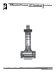
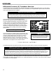
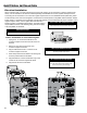
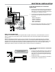
∆P Transducer to a LectroCount
7. Route the ∆P transducer cable through a cable gland in a
port on the back of the LectroCount register. Secure the
cable gland. LC recommends running the cable through a
cut to length piece of weatherproof conduit.
8. Connect the four ∆P transducer wires to terminal block J3
on the LectroCount register CPU board and J16 on the
81944 board.
• Black to J3 terminal 46
• White to J3 terminal 51
• Yellow to J16 terminal 57
• Blue to J16 terminal 58
• Red to J16 terminal 59
9. Run the red jumper wire (provided with the ∆P transducer
kit) from the J8 terminal 32 to J16 terminal 59 (+5V).
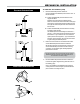
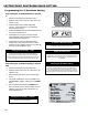
The shutdown device should
draw no more than 1 A.
J13 Terminal
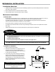
WIRING THE SHUTDOWN DEVICE
Typically, a ∆P transducer operates in conjunction with an output control circuit or a shutdown device, such as a
valve or a dead-man. The shutdown control must also be wired to the LectroCount register and should draw no
more than 1 A.
When the programmed shutdown value is met or exceeded, the LectroCount register depends on the shutdown
device to end the delivery. If the differential pressure meets or exceeds the shutdown differential pressure value
programmed into the LectroCount register, the register signals the shutdown device, and the shutdown device ends
the delivery. If no shutdown device is present and the shutdown value is met, the LectroCount register will stop
registering the delivery and print out a delivery ticket, but fuel will continue to be dispensed.
shutdown control device to a LectroCount
1. Route two wires (AWG determined by device) cable from
the shutdown control device through a cable gland in a
port on the back of the LectroCount register. Secure the
cable gland. LC recommends running the cable through
weatherproof conduit.
2. Connect the two wires from the shutdown control device
to terminal block J13, terminals 14 and 15.
ELECTRICAL INSTALLATION
11 12 13
PRINTER SERIAL 485 TERMINAL
POWER
COUNTER
MH1
CTS RXD TXD RTS GNDGND 485+A485-B CTS RXD TXD RTS +VP
EARTH
GND
GND
IN 1
IN 2
IN 3
IN 4
+5V OUT
+VP
GND
+12-24V
MH4
J20
J6
J3J2J1
J7
J7
C2
24
25
∆P Transducer
+5V(Out)/Jumper (59 to 32
)
A/Blue (58)
+5V/Red (59)
B/Yellow (57)
GND/White (51)
+VP/Black (46)
B
LectroCount Board