
Instruction Manual

7
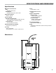
MECHANICAL INSTALLATION
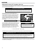
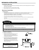
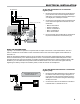
Correct Orientations
Incorrect Orientations
To install the ∆
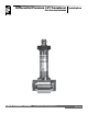
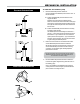
4. Mount the differential pressure transducer.
Inletandoutletttingsofthedifferentialpressuretransducerare¼”-18
NPT,femalethreads.
4a. Position the differential pressure transducer in an
upright orientation.
Regardlessofthetubingusedforthedifferentialpressure
transducerconnections,thetransducershouldbemountedupright
withthepressureimpulsepipinghorizontaltothettingsasshown
totheright.Thetransducermaybelocatedaboveorbelowthefull
owfuelmonitor.
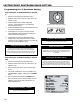
4b. Position the differential pressure transducer correctly
according to ow direction.
Thedifferentialpressuretransducerttingsaremarkedwitha“+”
signanda“-”signtoindicateupstreamanddownstreampressure.
Ensurethatthe“+”signisorientedsothatitisconnectedtothe
upstreampressuresidetubingandthe“-”signisconnectedtothe
downstreampressuresidetubing.Ifitisreversed,thiswillresultin
anegativereadingofthedifferentialpressure.
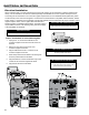
5. Fill the tube connections from the full ow fuel monitor
and the differential pressure transducer with uid.
Withthesystempressurized,carefullyloosentheconnectiononthe
inletsideofthedifferentialpressuretransducerwithoutremoving
itcompletely.Onceuidappears,tightenthetting.Repeatthis
procedurefortheoutletside.
6. Route the differential pressure transducer cable to the
LectroCount register. Register wiring instructions are on
the following page.
Ifthisisanewinstallationandthedifferentialpressuretransducer
isalreadywiredtotheLectroCountregister,proceedthedifferential
pressureshutdowncircuitwiringinstructions.
The tube connections from the full ow fuel monitor and the
differential pressure transducer must be lled with uid for
the transducer to function properly.