CIM 100 Turbine Meter and Integral Register Liquid Controls Group An IDEX Fluid & Metering Business Installation and Operation IEM100-40
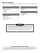
Table of Contents Introduction Maintenance Safety........................................................................ 3 Principles of Operation.............................................. 5 Pickup Coil................................................................ 5 Specifications............................................................ 6 Dimensions............................................................... 6 Disassembly..............................................................
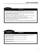
Safety Procedures Be Prepared ! WARNING • Before using this product, read and understand the instructions. • All work must be performed by qualified personnel trained in the proper application, installation, and maintenance of equipment and/or systems in accordance with all applicable codes and ordinances.
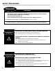
Safety Procedures Safely Evacuate Be Prepared Piping System ! WARNING Before disassembly of any meter or accessory component: • All internal pressures must be relieved and all liquid drained from the system in accordance with all applicable procedures., • Pressure must be 0 (zero) psi. • Close all liquid and vapor lines between the meter and liquid source. For Safety Rules Regarding LPG, refer to NFPA Pamphlet 58 and local authorities.
Principles of Operation Principles of Operation 1. The precision turbine flowmeter is a volumetric flow measuring device. 2. Fluid flowing through the flowmeter engages the vaned rotor and causes it to rotate at an angular velocity proportional to the flow rate. 3. The rotating vanes pass by the pickup coil and generate an electrical signal (AC sine wave type). The sum of the pulsing electrical signal relates directly to the flow rate. 4.
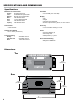
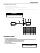
Specifications and Dimensions Specifications Materials of Construction Housing: Cover: Bearings: Shaft: Rotor: Cone: Clip Assy: Anodized Aluminum UV Resistant Polycarbonate Phenolic Thermoset Plastic 316 Stainless Steel 17-4 PH Stainless Steel 316 Stainless Steel 316 Stainless Steel Flow Rate • 5 to 50 GPM (19 to 190 LPM) Display • LCD • 8 digits • 5 decimal point selections • Scaled in optional liters, gallons, or cubic meters Connections • 1" NPT Female Accuracy Temperature Rating Power
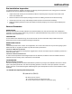
Installation Pre-installation Inspection Your turbine flowmeter is capable of providing you with high precision performance over a long period. It should be treated with care and not subjected to rough handling. 1. Unpack the flowmeter carefully. Use the information contained on the packing slip to verify proper model number, serial number, and calibration data. 2. Remove the instrument from the plastic packaging and remove the endfitting protectors from the flowmeter housing. 3.
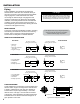
Installation Piping Proper installation of the flowmeter minimizes the harmful effects of fluid swirl. The rotational velocity of the rotor is a function of the fluid velocity and the blade angle engagement. Fluid swirl ahead of the meter can change the effective angle of engagement and cause the measurement to deviate from the supplied calibration, which was performed under controlled flow conditions.
Maintenance Turbine Meter Disassembly 1. Remove lock nut from shaft end on the inlet side. 2. Insert extraction hook into inlet clip assembly and extract with a parallel pulling motion. 3. Remove cone, bearings and rotor. 4. Remove outlet clip assembly with extraction hook as directed in step 2. Do not remove lock nut from outlet side clip assembly. Leave clip, cone, shaft and nut assembled. (Refer to diagram) Assembly Notes 1. Removal of internals should be performed in a clean area. 2.
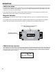
Operation CIM100 Run Mode The CIM100 user interface consists of two modes, the run mode, which is for everyday metering, and the menu mode, which is for setup, calibration, and diagnostics. In run mode, the CIM100 display shows a running totalizer, the unit of measurement, and any active indicator lights. Run mode is active only when the Chassis Intrusion button is held down. In normal operation, the CIM100 cover, fastened flush to the housing, holds the Chassis Intrusion button down.
Operation CIM100 Menu Mode The menu mode consists of 12 options for diagnosing, setting up, and calibrating the CIM100. Three small red buttons provide the means to navigate and edit inside the menu mode. A fourth red button switches the display between run and menu mode.
Operation Menu Mode Options Run Mode Violation When the CIM100 cover is removed and the Chassis Intrusion button releases, the CIM100 will enter an error state. The CIM100 display will flash between a “violated” message, shown on the left, and the run mode totalizer. Press the Select button to proceed to the Reset Chassis Intrusion option. Reset Chasiss Intrusion The Reset Chassis Intrusion option returns the CIM100 to run mode. To return the CIM100 to run mode: 1.
Chassis ntrusion Operation Menu Mode Options Digit GRAND GAS Select GALLITM3 X100 LCD Test This option illuminates all segments of the CIM100’s LCD display. Press the Select button to activate the LCD test. Software Version Menu This option displays the current version of CIM100 software. Menu Lockout Enable This option enables and disables the menu lockout.
Calibration Calibrating the CIM100 1. Calibrate the CIM100 with a volumetric prover. 2. Determine the C-factor. 3. Enter the C-factor into the CIM100 C-factor field. 1. Calibrate the CIM100 with a volumetric prover. 1. Remove the CIM100 cover. 2. Scroll to the Decimal option and set the decimal display to hundreths (0.00) 3. Scroll to the C-factor option and enter the approximate C-factor. Enter 1.377410.3 for gallons. Enter 5.208333.3 for litres. 4.
Calibration Calibrating the CIM100 3. Enter the C-factor into the CIM100 C-factor field. 1. Press the Menu until the C-factor field appears. 2. Press the Select button to display the current C-Factor. 3. Enter the new calculated C-factor into the field. The 0.005208396 value from the example would be entered as 5.208396.3 in the CIM100 C-factor field.
Liquid Controls 105 Albrecht Drive Lake Bluff, IL 60044 (847) 295-1050 Liquid Controls Europe/SAMPI Via Amerigo Vespucci 1 55011 Altopascio (Lucca), Italy +39 0583 24751 IDEX Fluid and Metering Pvt. Ltd. Survey No. 256, Alindra Savli GIDC, Manjusar Dist.