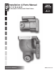
Installation & Parts Manual K-7, K-15, & K-30 Air Actuated & Differential Check Valves Installation: M400-30 www.lcmeter.
Table of Contents Description Page Number General Information .................................................. 2 Specifications ............................................................ 3 K-7 Valves ................................................................. 4-5 Installation ................................................................. 4 New Installations ....................................................... 4 Retrofit Installations ...................................................
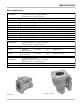
Specifications Model/Applications K-7 Va lve s: Used on M-5 & M-7 - 1½" & 2" Meters Maximum Flow Rate = 150 gpm (568 lpm) W orking Pressure: 150 psi (10.5 bar) Mode l No.
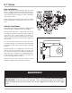
K-7 Valves New Installations When ordered with a new metering system, the Check Valve is supplied mounted to the metering system as shown to the right. A line must be connected to the flange on the outlet side of the 2-stage, preset valve. This flange connection is 2” NPT. Finally, install a vent line from one port of the check valve to the air eliminator. Plug the other side of the check valve.
K-7 Valves Disassembling the K-7 Valve NOTE: Refer to the illustrated parts breakdown to the right for Item Numbers referenced in these instructions. Item Numbers appear in circles in the drawing. 1 Use a fixture to press and hold the piston (Item 220) in place with the compression spring (Item 389) compressed. 2 Loosen the three screws (Item 615) that hold the seal ring (Item 354).
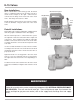
K-15 Valves New Installations Mechanical Register When ordered with a new metering system, the Check Valve is supplied mounted to the metering system as shown in the example to the right. A line must be connected to the flange on the outlet side of the check valve. This flange connection is 3” NPT. Air Eliminator V-15 Valve Finally, install a vent line from one port of the check valve to the air eliminator. Plug the other side of the check valve.
K-15 Valves Disassembling the K-15 Valve NOTE: Refer to the illustrated parts breakdown to the right for Item Numbers referenced in these instructions. Item Numbers appear in circles in the drawing. 1 Use a fixture to press and hold the valve check guide (Item 14) in place with the compression spring (Item 15) compressed. 2 Remove the two screws (Item 2). 3 Release the pressure from the check valve guide (Item 14) until the spring (Item 15) exerts NO pressure.
K-30 Valves The K-30 check valve is used on M-30 3” meters. The K30 check valve is a combination of the K-15 check valve Model A3845 and a pipe nipple assembly. The nipple assembly includes two flanges. One flange is 6” square with a 3” NPT thread, the other is 4.75” square with a 3” NPT thread. The pipe nipple is 3” in diameter and 4” in length. The pipe nipple assembly is included in order to mount the check valve to the meter as the meter connection is larger than the check valve connection.
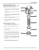
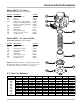
Illustrated Parts Breakdown Model A2817: K-7 Valve Used with M-5 & M-7, 1½” & 2” meters. Item No. 110 220 354 389 430 465 475 615 626 715 Description Air Check Housing Piston Seal Ring Compression Spring (A2817) Compression Spring (A28171) Compression Spring (A28172) Flange Gasket Quad Ring Name Plate Screw, #6-32-3A (3) Screw, .375-16 x 1.25 (4) Flat Washer (4) Part No.
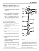
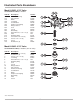
Illustrated Parts Breakdown Model A3830: K-15 Valve Used with M-15 & M-25, 3” meters. Item No. 110 133 138 350 354 382 420 452 455 465 521 540 572 615 626 678 738 Description Air Check Housing Cup & Piston Guide Lock Ring Seal Retainer Compression Spring Flange Gasket Seal U-Cup Quad Ring Heli-Coil Insert, .5-13 x .5 (4) Plate Retaining Ring Screw, #10-14 x .375 (2) Screw, .5-13 x 1.5 (4) Screw Flat Washer (4) Part No.
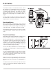
Illustrated Parts Breakdown Model A4845: K-30 Valve Used with M-30, 3” meters. Item No. Description 1 K-15 Air Check Valve Assy (See Page 9 for A3845 Parts.) 2 Flange, 3” 3 Pipe Nipple 5 Flange, 3” NPT 6 Screw, .5-13 x 2.75 (4) 7 Hex Nut, .5-13 (4) 8 Flange Gasket 9 Flange Gasket 11 Screw, .625-11 x 2.5 (4) 12 Flat Washer (6) 13 Flat Washer (4) 14 Lock Washer (2) Part No.
A Unit of IDEX Corporation 105 Albrecht Drive Lake Bluff, IL 60044-2242 1.800.458.5262 • 847.295.1050 Fax: 847.295.1057 www.lcmeter.com © 2005 Liquid Controls Pub. No.