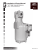
Installation & Parts Manual 2" & 3" High Capacity Strainers For Class 1, Petroleum Applications Installation: M200-20 www.lcmeter.
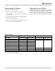
Table of Contents Description Page Number Introduction ......................................................... 2 What LC Strainers Do ............................. 2 How LC Strainers Work .......................... 2 Features ................................................. 2 Installation ........................................................... 3 Maintenance ........................................................ 4-5 Torque Chart .......................................................
Installation Flush All New Systems Installing Flushing the system before the meter has been installed is the preferred first step. Install the strainer on the inlet side of the meter. Bolt the strainer outlet to the inlet flanged connection of the meter. Then bolt the inlet piping to the inlet flanged connection of the strainer. For new systems that don’t currently have a meter installed, thoroughly flush the lines until the system is purged of all foreign materials.
Maintenance ! WARNING All internal pressures must be relieved before disassembly of the meter, strainer, air eliminator, any valves in the system, the pulse output device, or the front and rear covers. LINE PRESSURE MUST BE 0.0 PSI. Refer to your meter manual for instructions on reducing the internal pressure. Personal injury or death may result from working on a system under pressure.
Maintenance Reassembling the Strainer Tightening Screws and Nuts ( See Page 7 For Item Numbers) Leakage that occurs after tightening the fasteners indicates a damaged seal or distortion to the surface of the cover. In either of these cases, the seals or cover must be replaced. Excessive tightening will not stop the leakage. See chart below for proper torque standards. 1. Place the strainer basket into the housing. 2. Place the end cover O-Ring (4) in the groove in the end cover (2). 3.
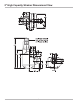
2" High Capacity Strainer Dimensional View 6
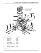
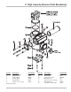
2" High Capacity Strainer Parts Breakdown Item No. 1 2 3 4 5 7 8 9 10 11 12 13 Description Housing, Hi-Cap Strainer Cover O-Ring, Buna O-Ring, Buna O-Ring, Buna Screw, .5-13 x 1.5 (4) Flat Washer (4) Screw, .375-16 x 1.25 (4) Flat Washer (4) Name Plate Screw, #2 x .19 (2) Pipe Plug, .
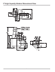
3" High Capacity Strainer Dimensional View 8
3" High Capacity Strainer Parts Breakdown Item No. 1 3 4 5 6 8 Description Housing, Hi-Cap Strainer Cover O-Ring, Buna O-Ring, Buna O-Ring, Buna Screw, .5-13 x 1.5 (8) Part Number N/S* 42987 06847 06798 04474 06057 Item No. 9 10 11 12 13 14 15 *N/S: Not for Sale 9 Description Flat Washer (8) Name Plate Screw, #2 x .19 (2) Mounting Foot Screw, .375-16 x .625 (4) Flat Washer (4) Pipe Plug, .
Troubleshooting PROBLEM 1 PROBLEM 2 Meter lockup- rotors to do not turn. Meter inspection due to meter inaccuracy revealed scoring of the meter chamber. PROBABLE CAUSE Strainer basket rupture possibly due to improper maintenance of the strainer basket. If this occurred in a new system, the system may have been improperly flushed. PROBABLE CAUSE See the probable causes for Problem 1. SOLUTION See the solutions for Problem 1.
Troubleshooting PROBLEM 3 PROBLEM 4 High pressure drop across the strainer or loss of flow rate. Leaking at the strainer basket cover. PROBABLE CAUSE The seals are allowing product to leak. This is caused by a damaged O-Ring or gasket seal, or reusing a Teflon seal after strainer maintenance. PROBABLE CAUSE Strainer basket screen is partially blocked by foreign material such as dried material or salted out solid particles due to drying. SOLUTION Replace the damaged seals.
A Unit of IDEX Corporation 105 Albrecht Drive Lake Bluff, IL 60044-2242 1.800.458.5262 • 847.295.1050 Fax: 847.295.1057 www.lcmeter.com © 2005 Liquid Controls Pub. No.