LIPPERTCOMPONENTS XL HYDRAULIC SLIDEOUT AND HYDRAULIC LANDING GEAR (HLG) SYSTEM OPERATION AND SERVICE MANUAL
TABLE OF CONTENTS SYSTEM……………………………………………........….….. Warning…………………………………........…….... Prior to Operation…………………….......……… Description………………………………........…….. Preventative Maintenance……….......……….. System Maintenance.................................... 3 3 4 4 5 6 OPERATION-SLIDEOUTS………….……........…………… 8 Warning......................................................... 8 Extending Slideout Room….............…………. 9 Retracting Slideout Room…….............……... 9 Auxiliary Operation……………............
SYSTEM WARNING FAILURE TO ACT IN ACCORDANCE WITH THE FOLLOWING MAY RESULT IN SERIOUS PERSONAL INJURY OR DEATH. THE LIPPERT XL HYDRAULIC SLIDEOUT AND HLG SYSTEM IS INTENDED FOR THE PURPOSES OF EXTENDING AND RETRACTING THE SLIDEOUT ROOM AND LEVELING THE UNIT. THE USE OF THIS SYSTEM FOR ANY REASON OTHER THAN WHICH IT IS INTENDED IS PROHIBITED BY LIPPERT’S LIMITED WARRANTY AND MAY RESULT IN SERIOUS PERSONAL INJURY OR DEATH.
PRIOR TO OPERATION The leveling system shall only be operated under the following conditions: 1. The coach is parked on a reasonably level surface. 2. Be sure all person, pets and property are clear of the coach while Lippert XL Hydraulic Slideout and HLG System is in operation. 3. Unit must be leveled prior to extending the slideouts to ensure coach will not move during operation of Slideout System and to provide the unit with a firm foundation. 4. Be sure battery is fully charged.
PREVENTATIVE MAINTENANCE PROCEDURES The Lippert XL Hydraulic Slideout and HLG System has been designed to require very little maintenance. To ensure the long life of your system, read and follow these few simple procedures. 1. Change fluid every 36 months (in reservoir ONLY!). a) Check fluid only when jacks and slideouts are fully retracted. b) Always fill the reservoir with the jacks and slideouts are in the fully retracted position.
SYSTEM MAINTENANCE The Lippert XL Hydraulic Slideout and HLG System has been static tested to over 6,000 continuous cycles with out any noticeable wear to rotating or sliding parts. It is recommended that when operating in harsh environments (road salt, ice build up, etc.) the moving parts be kept clean and can be washed with mild soap and water. No pertroleum-based grease or lubrication is necessary and in some situations may be detrimental to the environment and long term dependability of the system.
NOTE: The Lippert XL Hydraulic Slideout and HLG System is designed to operate as a negative ground system. A negative ground system utilizes the chassis frame as the ground source. An independent ground wire back to the battery is not needed. It is important the electrical components have good wire to chassis contact. Over 90% of unit electrical problems can be attributed to bad ground connections.
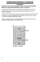
OPERATION-HYDRAULIC SLIDEOUT WARNING FAILURE TO ACT IN ACCORDANCE WITH THE FOLLOWING MAY RESULT IN SERIOUS PERSONAL INJURY OR DEATH. ALWAYS MAKE SURE THAT THE SLIDEOUT ROOM PATH IS CLEAR OF PEOPLE AND OBJECTS BEFORE AND DURING OPERATION OF THE SLIDEOUT ROOM. ALWAYS KEEP AWAY FROM THE SLIDE RAILS WHEN THE ROOM IS BEING OPERATED. THE GEAR ASSEMBLY MAY PINCH OR CATCH ON LOOSE CLOTHING CAUSING PERSONAL INJURY. INSTALL TRANSIT BARS (IF SO EQUIPPED) ON THE SLIDEOUT ROOM DURING STORAGE AND TRANSPORTATION. Fig.
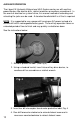
EXTENDING SLIDEOUT ROOM 1. 2. 3. 4. Level the unit. Verify the battery is fully charged and hooked-up to the electrical system. Remove the transit bars (if so equipped). Press and hold the IN/OUT switch (Fig. 2) in the OUT position until the room is fully extended and stops moving. 5. Release the switch, which will lock the room into position. RETRACTING SLIDEOUT ROOM 1. Verify the battery is fully charged and hooked-up to the electrical system. 2. Press and hold the IN/OUT switch (Fig.
AUXILIARY OPERATION The Lippert XL Hydraulic Slideout and HLG System can be run with auxiliary power devices like electric drills, ratchet wrenches or cordless screwdrivers. In the event of electrical or system failure, this manual method of extending and retracting the jacks can be used. A standard handheld drill is all that is required. NOTE: It is suggested to use a power drill running on AC power instead of a corless drill with a rechargeable battery pack.
OPERATION-HYDRAULIC LANDING GEAR WARNING FAILURE TO ACT IN ACCORDANCE WITH THE FOLLOWING MAY RESULT IN SERIOUS PERSONAL INJURY OR DEATH. ALWAYS MAKE SURE THAT THE LANDING GEAR AREA IS CLEAR OF PEOPLE AND OBJECTS BEFORE AND DURING OPERATION OF THE LANDING GEAR. ALWAYS KEEP AWAY FROM THE LANDING GEAR WHEN THE SYSTEM IS BEING OPERATED. SERIOUS PERSONAL INJURY OR DEATH MAY OCCUR. The Lippert XL Hydraulic Slideout and HLG System employs a system of manually leveling the unit.
SERVICE FLUID FILLING PROCEDURE Fig. 7 Fill Cap The Lippert XL Hydraulic Slideout and HLG System uses automatic transmission fluid (ATF). Any ATF can be used. A full synthetic or synthetic blend works best such as Dexron II, Dexron III or Mercon 5. For best operation, fill system within 1” of the top when all slideouts and landing gear are completely retracted. The see through reservoir makes it easy to check oil level. It is recommended that the oil level be checked prior to operating the system.
MECHANICAL ROOM ADJUSTMENT Vertical & Horizontal Room Adjustment NOTE: All slideout room adjustments must be performed by certified service technicians. Adjustments made by non-certified persons may void any and all warranty claims. Horizontal adjustment - See pg. 17, Fig. 8 1. Loosen 2 carriage bolts “A” on each bracket located at the end of each guide tube. 2.
MECHANICAL ROOM ADJUSTMENT Bolt “A” Bolt “A” Fig. 8 Nuts “A” Bolt “B” Fig.
MECHANICAL ROOM ADJUSTMENT-CONT. Jam Nut-1 Nylock Nut 2” - 3” FREE TRAVEL Jam Nut-2 Adjusting room so it seals in the IN position 1. Locate cylinder coming through the frame; 2. On the end of the cylinder there is a threaded shaft mounted to the drive bracket with 3 nuts. 3. Loosen the Jam Nut-1 and set Jam Nut-2 to desired location. 4. Tighten down the Nylock Nut against bracket. Make sure Jam Nut-2 is adjusted for “FREE TRAVEL” (see above). Secure assembly by tightening Jam Nut-1against Jam Nut-2.
SYNCHRONIZING ROOM TRAVEL Fig. 11 11a 11b The Lippert XL Hydraulic Slideout and HLG System room travel (both sides of the room traveling the same distance) can be adjusted with specially designed synchronizing bracket mounted on the passive slide tube. The passive slide tube is the one that is not powered. The active slide tube is the one that has the cylinder attached. If one side of the room fails to seal adjust as follows: 1. Loosen bolts (Fig. 11a) on top of the passive slide tube (Fig. 11b) 2.
REMOVING AND REPLACING CYLINDER Fig. 12 To replace cylinder: 1. Take measurements A and B. 2. Remove both nylock nuts (2 total) from threaded shafts on cylinder rod. 3. Take note of jam nut locations and remove. 4. After everything is disconnected, slide hydraulic cylinder out of frame. To replace with new cylinder, follow previous directions in reverse.
TROUBLESHOOTING Hydraulic Landing Gear (HLG).................................................21 Hydraulic Slideout System.......................................................21 Troubleshooting Chart - Slideouts..........................................22 Troubleshooting Chart - HLG...................................................22 Checking for Bad Cylinder.......................................................23 Power Unit.................................................................................
TROUBLESHOOTING-HLG The Lippert XL Hydraulic Slideout and HLG System is a feature that allows the owner more options and flexibility for quickly and effectively leveling his coach. It is a totally integrated system with your coach’s chassis and electronics. Every coach has it’s own personality and what may work to fix one coach may not work on another even if the symptoms appear to be the same. When something restricts mechanized travel, system performances will be unpredictable.
TROUBLESHOOTING CHART - SLIDEOUT The following troubleshooting chart outlines some common problems, their causes and possible corrective actions. When reference is made to a “Power Unit,” the term includes the motor and the actuator as a complete unit. All Power Units are shipped from the factory with a serial number and date code, which should be given to the service technician when asking for assistance.
TROUBLESHOOTING – CHECKING FOR BAD CYLINDER 1. Retract (close) the slideout (room) completely. 2. Loosen hose from “E” (extend) port on the manifold of the Power Unit. WARNING! Do not attempt to run room out with the “E” port hose loose. The system will experience RAPID FLUID LOSS. 3. Plug opening on manifold to prevent drawing air into the system. 4. Energize the Power Unit to retract (close) room. 5. Continue to run the room in and watch for fluid flow from hose/port “E”.
ORDERING PARTS To assist the customer service when ordering parts, please provide the following information: 1. Your Name 2. Company Name 3. Phone Number 4. Shipping Address 5. Billing Address 6. Purchase Order Number 7. Coach A. Serial # and/or VIN # B. Make C. Model 8. Part Number 9. Description 10. Quantity Please take your coach to an authorized service center for repairs.