Schwintek In-Wall™ Slideout System TROUBLESHOOTING GUIDE Rev: 01.30.
TABLE OF CONTENTS SYSTEM INOPERATIVE 3 Controller 3 Motors and Harnesses 4 ROOM STUCK OUT (RETAIL) 5 Electronic Manual Override 5 Disengage Motors, Manually Retract Room and Travel Lock ROOM STUCK IN (DEALER ONLY) 7 Electronic Manual Override 7 Remove Exterior Fascia to Access Motor Retention Screw VISUAL INSPECTIONS 8 9 Measurements 9 Floor Rollers 11 V-Rollers 11 Gear Racks Rev: 01.30.
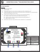
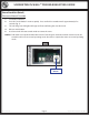
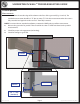
SCHWINTEK IN-WALL™ TROUBLESHOOTING GUIDE System Inoperative Controller 1. Locate Controller (Fig. 1). 2. Activate switch. 3. Look for the status LEDs on the controller to light while switch is activated (Fig. 1E). 4. If status LEDs light, but no error codes are present, skip to page 9 of this guide to do a visual inspection of the mechanical portions of this system. 5. If status LEDs do not light, and no error codes are present, check the following: A.
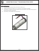
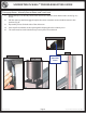
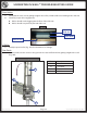
SCHWINTEK IN-WALL™ TROUBLESHOOTING GUIDE Motors and Harnesses 1. Check for proper connections between the motors and harnesses. 2. Visually inspect the exposed harnesses to ensure they are not pinched or damaged. 3. If test harness is available, connect the test harness from the controller to the motor and try to operate the slide-out using the normal switch. 4. If test harness is not available, ohm test the harness. Fig. 2 - Motor and Harness Rev: 01.30.
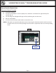
SCHWINTEK IN-WALL™ TROUBLESHOOTING GUIDE Room Stuck Out (Retail) Electronic Manual Override 1. Locate the controller. 2. Press the "mode button" six times quickly. Press and hold a seventh time for approximately five seconds (Fig. 3). 3. The red and green LED lights will begin to flash, confirming the override mode. 4. Release mode button. 5. Use the normal slide-out control switch to retract the room.
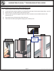
SCHWINTEK IN-WALL™ TROUBLESHOOTING GUIDE Disengage Motors, Manually Retract Room and Travel Lock 1. Bend back wipe seal. Visually locate motor and motor retention screw. Remove the screw (Figs. 4, 5 and 7). 2. Pull the motor up until disengaged. Replace the motor retention screw to hold the motor in this position (Fig. 6). 3. Repeat this process for both sides of the slide room. 4. Push or pull room back in to the opening while keeping the sides relatively even. 5.
SCHWINTEK IN-WALL™ TROUBLESHOOTING GUIDE Room Stuck In (Dealer Only) Electronic Manual Override 1. Locate the controller. 2. Press the "mode button" six times quickly. Press and hold a seventh time for approximately five seconds (Fig. 8). 3. The red and green LED lights will begin to flash, confirming the override mode. 4. Release mode button. 5. Use the normal slide-out control switch to extend the room.
SCHWINTEK IN-WALL™ TROUBLESHOOTING GUIDE Remove Exterior Fascia to Access Motor Retention Screw 1. Remove exterior fascia carefully so as not to damage it. 2. Locate and remove motor retention screw located near the top of each vertical column (Figs. 9 and 12). 3. Bend back wipe seal and visually locate motor (Fig. 10). 4. Pull the motor up until disengaged. Replace the motor retention screw to hold the motor in this position (Fig. 11). 5. Repeat this process for both sides of the slide room. 6.
SCHWINTEK IN-WALL™ TROUBLESHOOTING GUIDE Visual Inspections Measurements 1. Measure from the outside edge of the column to the face of the gear rack (Fig. 13 and 14). The standard measurement should be 2 1/2" plus or minus 1/8". Take this measurement when the room is fully extended and again when the room is 3" from fully retracted. Note: For units with non-standard installations, contact the OEM for their specific measurements. 2. Measure the gear racks for parallel.
SCHWINTEK IN-WALL™ TROUBLESHOOTING GUIDE Floor Rollers 1. Check that the seals are not getting caught in the rollers, which could cause binding to the slide-out. 2. Check for proper roller engagement: A. Rollers should not be digging into the floor of the slide-out. B. Rollers should not spin freely beneath slide-out. Fig. 15 Floor of Slide-out Floor Roller Floor of Unit V-Rollers 1. Visually inspect V-roller (Fig. 16D) for obstructions or damage. Gear Racks 1.
The contents of this manual are proprietary and copyright protected by Lippert Components, Inc. (“LCI”). LCI prohibits the copying or dissemination of portions of this manual unless prior written consent from an authorized LCI representative has been provided. Any unauthorized use shall void any applicable warranty. The information contained in this manual is subject to change without notice and at the sole discretion of LCI. Revised editions are available for free download from www.lci1.com.