Level-Up® (Towable) TROUBLESHOOTING GUIDE Rev: 11.04.
LEVEL-UP® (TOWABLE) TROUBLESHOOTING GUIDE TABLE OF CONTENTS Introduction Components 5th Wheel Operation 3 3 5 5 5 5 6 6 6 6 7 7 7 8 9 Auto Level Auto Level Sequence Hitch Recognition Travel Trailer Operation Unhooking Instructions Auto Level Auto Level Sequence Hitch Recognition Reconnecting the Unit to a Tow Vehicle Touch Pad Error Codes Wiring Diagram Parts Table Rev: 11.04.
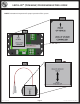
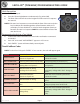
LEVEL-UP® (TOWABLE) TROUBLESHOOTING GUIDE Introduction Level-Up® is an Automatic Leveling system. This system is equipped with 14K Aluminum Front Jacks with 21” of travel and 8K Aluminum Leveling Jacks with 15” of travel. The jacks in the Level-Up® system work in pairs. Components Fig. 1 A K E B G C F H D I J Callout Description A Up Arrow - Scrolls up through the menu on LCD. B Down Arrow - Scrolls down through the menu on LCD. C Enter - Activates modes and procedures indicated on LCD.
LEVEL-UP® (TOWABLE) TROUBLESHOOTING GUIDE Note: Orientation is imperative for proper operation of the system. Fig. 2A Fig. 2 Fig. 3A Fig. 3 Rev: 11.04.
LEVEL-UP® (TOWABLE) TROUBLESHOOTING GUIDE 5th Wheel Operation Fig. 4 Auto Level Note: Prior to unhitching from the tow vehicle, ensure unit is parked on a level surface and to chock the tires of the unit. 1. After unhitching from tow vehicle press Auto Level (Fig. 1F). Note: In order for hitch recognition feature to function, the auto level sequence MUST be started with the front of the unit above level. A Auto Level Sequence 1.
LEVEL-UP® (TOWABLE) TROUBLESHOOTING GUIDE Travel Trailer Operation Unhooking Instructions Note: Prior to unhitching from the tow vehicle, ensure unit is parked on a level surface and chock the tires of the unit. 1. Push “On/Off” button to turn system “On” (Green Light). 2. Push “Up” or “Down” arrow to scroll through features to “Manual Mode” in display. 3. Push “Enter”. 4. Push “Front” button to extend front jacks to the ground until the trailer is unhitched from the tow vehicle. Fig.
LEVEL-UP® (TOWABLE) TROUBLESHOOTING GUIDE Hitch Recognition Fig. 8 1. Turn on Touchpad. 2. Press the left and right buttons simultaneously (Fig. 8A and 8B). 3. The front of the unit will raise to the height where the auto level sequence was started. A B Note: If the auto level sequence was started with the front of the unit in a below level condition, the Hitch Recognition will not function and the LCD will display “Feature Disabled”.
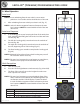
LEVEL-UP® (TOWABLE) TROUBLESHOOTING GUIDE Wiring Diagram Fig. 9 Note: See page 9 for parts table. C A B F E D H G K M I M M J L M N Rev: 11.04.
LEVEL-UP® (TOWABLE) TROUBLESHOOTING GUIDE Parts Table Callout Description A Touchpad B Touchpad Harness C Controller D Rear Sensor E Rear Sensor Harness F Main Harness (See below for color codes) Green - Extend Spade on dual polarity solenoid Yellow - Retract Spade on dual polarity solenoid Red - Power (Controller power with 10 amp in-line fuse) Blue - Curb Side Leveling Jacks (Connects to Valve Coil on extend manifold) Purple - Road Side Leveling Jacks (Connects to Valve Coil on extend manifold) Gray - Lea
All information contained within may be distributed as a full document only, unless otherwise permitted by explicit consent of Lippert Components Inc. to distribute individual parts. All information contained within is subject to change without notice. New editions will be posted on www.lci1. com and can be downloaded for free. Information contained within is considered factual until made obsolete by a *NEW* revision. Please recycle all obsolete materials.