LCI L����-U� M�������� L������� (2013-P������) OWNER'S MANUAL Rev: 08.11.
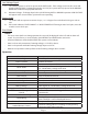
TABLE OF CONTENTS SYSTEM 3 3 3 4 4 4 5 6 7 7 7 7 8 8 8 9 9 9 10 10 10 10 11 11 13 13 14 14 14 15 17 18 19 Prior to Operation System Description Component Description Fluid Recommendation Preventative Maintenance Procedures Aluminum Jacks Power Unit Components CONTROLS Features System Wiring Requirements Air and Auxiliary Features Level Zero Point Calibration For Diesel Units with Air Bag Suspensions ONLY: Miscellaneous Low Voltage Signal Excess Slope Error Mode OPERATION Selecting a
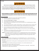
System Failure to act in accordance with the following may result in serious personal injury or death. The use of the LCI Level-Up Motorhome Leveling System to support the coach for any reason other than which it is intended is prohibited by Lippert's Limited Warranty. The LCI Level-Up Motorhome Leveling System is designed as a "Leveling" system only and should not be used to provide service for any reason under the coach, such as changing tires or servicing the leveling system. Lippert Components Inc.
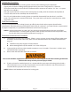
Component Description The LCI Level-Up Motorhome Leveling System consists of the following major components: Lippert jacks are rated at a lifting capacity appropriate for your coach. Each jack has a 9” diameter (63.5-square-inch) shoe on a ball swivel for maximum surface contact on all surfaces. (12” dia. - 113-squareinch shoe also available.) Each jack is powered from a central 12V DC motor/pump assembly, which also includes the hydraulic oil reservoir tank, control valve manifold, and solenoid valves.
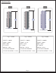
Aluminum Jacks Fig. 2 Fig. 1 H Fig. 1 - 195860 Fig. 3 H Fig. 2 - 236560 H Fig. 3 - 258550 CAPACITY - 8,000 lb. CAPACITY - 14,000 lb. CAPACITY - 20,000 lb. STROKE - 15.00 in. STROKE - 15.13 in. STROKE - 16.00 in. BORE - 2.00 in. BORE - 2.50 in. BORE - 3.00 in. H - 21.375 in. H - 21.50 in. H - 23.063 in. ROD DIA. - 1.50 in. ROD DIA. - 1.875 in. ROD DIA. - 2.25 in.
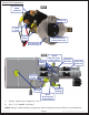
Power Unit Components Fig. 4 Motor Solenoid Plastic Cap 12v DC power Ground Power Manual Override (under plastic cap) 12v DC motor Fig. 5 Extend Fittings Quick Disconnect for Flush and Fill Hydraulic Manifold Valve and Valve Coil Pressure Switch Return Fittings Fill Cap Quick Disconnect for Flush and Fill 1. Fittings - High Pressure O-Ring Face - Size 4 2. Hose - ¼" I.D. 3000PSI - W.P.
Controls Features • Automatic extension of jacks from full retract position (with automatic ground detection). • Automatic leveling of jacks. • Manual leveling of jacks. • Automatic retraction of jacks (with automatic full retract detection). • Air bag suspension features (configurable on/off). • Emergency retract/user alarm mode (jacks not retracted and park brake disengaged). • Automatic jack error detection and error mode. • Configuration mode for Air features.
Level Zero Point Calibration Before auto leveling features are available, the Level Zero point must be set. This is the point to which the system will return when an auto leveling cycle is initiated. To set the zero point (controller module must be fully secured in production-intent location), first run a manual leveling sequence to get the vehicle to the desired level point. Then activate the Level Zero point configuration mode. This mode is enabled by performing the following sequence: 1. Turn panel off.
Low Voltage Signal 1. The vehicle requires 12.7V DC to operate in the AUTO mode. If the voltage is too low, the screen will display LOW VOLTAGE. If voltage drops below 12.7V DC, the system will only operate in the MANUAL MODE and continue to display LOW VOLTAGE. 2. Minimum Voltage - If voltage drops below 9.5V DC during AUTO or MANUAL operation LOW VOLTAGE will appear in the screen and the system will cease operating. Excess Angle 1. The control will not operate at extreme slopes, i.e. 3.
Selecting a Site When the coach is parked on an excessive slope the leveling requirements may exceed the jack lift stroke capability. If the coach is parked on an excessive slope, the coach should be moved to a more level surface before the leveling system is deployed. EXCESS ANGLE will appear on the LCD screen if the coach is 3.5 degrees out of level front to rear or side to side. See Page 9. Automatic Leveling Procedure Note: Refer to Fig.
Manual Leveling Procedure Note: When leveling your coach, the coach should be leveled from FRONT TO REAR first (step 2-4). When the coach is level from FRONT TO REAR, then level the coach from LEFT TO RIGHT (step 5). Note: Coach requires 12.7V DC to commence auto leveling function. If voltage at the power unit is not 12.7V DC, run the engine. 1. Push ON/OFF button on control panel. The system is now operational and the ON/OFF light will be lit. 2. Push DOWN ARROW to display MANUAL LEVEL on the screen.
Fig. 6 A K E B G C F H D I J Callout A B C D E F G H I J K Rev: 08.11.2014 Description Up Arrow - Scrolls up through the menu on LCD. Down Arrow - Scrolls down through the menu on LCD. Enter - Activates modes and procedures indicated on LCD. Retract - Places leveling system into retract mode. - Manual mode ONLY LCD Display - Displays procedures and results. Auto Level - Places leveling system into auto level mode. Front Jack Button - Activates both front jacks in manual mode.
Manual Override - Jacks In the event that the jacks will not extend or retract, the valves can be manually overridden by using a 5/32” hex wrench to turn the manual override clockwise on the valve (See Fig. 7). The leveling jacks can then be extended or retracted. Remember to turn the manual override completely counterclockwise (See Fig. 8) until it will no longer turn to close the valve after the jacks have been completely extended or retracted.
Automatic Safety Shutoff If the control panel is left on and inactive for four minutes it will shut off automatically. To reset the system, the coach ignition must be turned off, then back on, and the ON/OFF button must again be pushed. Drive Away Protection System If the ignition is in the “RUN” position, jacks are down, and the operator releases the parking brake, all indicator lights will flash and the alarm beeper will activate.
Fluid Recommendations for Hydraulic Leveling 1. Operation at air temperatures routinely above 0oC (32oF) • Dexron 3/Mercon ATF • Mercon 5 ATF • Dexron 6 ATF • PetroBlend (Mason City, IA) PHO 0022S (synthetic group 3 base blend) • Bellman All Temp 22 (Bremen, IN) • Or any ATF or hydraulic fluid with a pour point lower than -42oC (-45oF) 2.
Problem Probable Cause Coach ignition not in RUN position System will not turn on and Parking brake not set On/Off indicator light does Controls have been not illuminate on for more than four minutes and have timed out Control panel turns on but turns off when jack button Low voltage on battery is pushed or displays "Low Voltage" Control panel turns on, coach will not auto level, Low fluid level "Jacks Down" displayed, jacks are retracted Little to no fluid in reservoir Leg valve is inoperative Jacks will
Plumbing Diagram Fig. 11 5A 3 1 5 7 6 2 4 6A NOTE: HOSE KIT - 293728; Hoses will vary in length by coach model. Measure hose and consult LCI Service; Hose Specs. 3000 p.s.i.; 1/4” in. I.D. A. Leveling Jack EXTEND ports (Fig. 12A) Fig. 12 B. Leveling Jack RETRACT ports (Fig. 12B) 1. Left (Road) Rear - Black Hose - BLUE Valve Wire 2. Left (Road) Front - Black Hose - GREEN Valve Wire 3. Right (Curb) Rear - Black Hose - RED Valve Wire 4. Right (Curb) Front - Black Hose - PURPLE Valve Wire 5.
Wiring Diagram Fig. 13 Rev: 08.11.
12-PIN WIRE HARNESS (Fig. 14) 1. WHITE (CHASSIS POWER) 2. BLACK W/ WHITE(PUMP SOLENOID) 3. REAR VALVE) 7. BROWN (GROUND) 8. PURPLE (CURBSIDE 11 8 7 FRONT VALVE) RED (CURBSIDE REAR VALVE) 9. GREEN (ROADSIDE FRONT VALVE) 10. AUX 5. YELLOW (PSI SWITCH) 11. AUX 6. BLUE (ROADSIDE 12. AUX 4. 12 Fig. 14 Fig.
All information contained within may be distributed as a full document only, unless otherwise permitted by explicit consent of Lippert Components Inc. to distribute individual parts. All information contained within is subject to change without notice. New editions will be posted on www.lci1. com and can be downloaded for free. Information contained within is considered factual until made obsolete by a *NEW* revision. Please recycle all obsolete materials.