LCI ELECTRONIC/HYDRAULIC LEVELING � SLIDEOUT OWNER'S MANUAL Rev: 07.14.
TABLE OF CONTENTS System System Description Component Description LCI Hydraulic Jacks Steel Jacks - Bi-rotational Power Unit Aluminum Jacks - Unidirectional Power Unit Leveling System Controls Leveling Features System Wiring Requirements Air and Auxiliary Features Touchpad Schematic Level Zero Point Calibration "Latched Out" Warning Air and Auxiliary Feature Configuration Error Mode User Alarm Mode Miscellaneous Prior to Operation Operation Selecting A Site Automatic Leveling
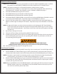
System Failure to act in accordance with the following may result in death or serious personal injury. The use of the Lippert Electronic/Hydraulic Leveling and Slideout System to support the coach for any reason other than which it is intended is prohibited by Lippert's Limited Warranty.
Component Description The Lippert Electronic/Hydraulic Leveling and Slideout System consists of the following major components: Lippert jacks are rated at a lifting capacity appropriate for your coach. Each jack has a 9” diameter (63.5 square inch) shoe on a ball swivel for maximum surface contact on all surfaces. (12” dia. - 113 sq. in. shoe also available).
Leveling System Controls Leveling Features • Automatic extension of jacks from full retract position (with automatic ground detection). • Automatic leveling of jacks. • Manual leveling of jacks. • Automatic retraction of jacks (with automatic full retract detection). • Air bag suspension features (configurable on/off). • Emergency retract/user alarm mode (jacks not retracted and park brake disengaged). • Automatic jack error detection and error mode. • Configuration mode for Air features.
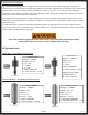
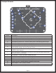
Touchpad Schematic Fig. 5 A C B E O J D N K L F G H P M I Callout A B C D E F G H I J K L M N O P Rev: 07.14.2014 Description Manual Operation - Places control panel in manual operation mode. Manual Operation LED - Indicates control panel in manual operation mode. Automatic Operation - Places control panel in automatic operation mode. Automatic Operation LED - Indicates control panel in automatic operation mode. Wait LED - Indicates to the operator to pause operation until the LED turns off.
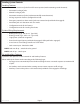
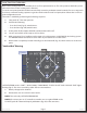
Level Zero Point Calibration Before auto-leveling features are available, the Level Zero point must be set. This is the point to which the system will return when an auto leveling cycle is initiated. To set the zero point (controller module must be fully secured in production-intent location), first use a carpenter's level to run a manual leveling sequence to get the vehicle to the desired level point; then activate the Level Zero point configuration mode.
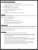
Air and Auxiliary Feature Configuration For Diesel Units with Airbag Suspensions ONLY: • Feature is entered ONLY after zero mode programming. • At this point the WAIT LED (Fig. 5E) will blink for 20 seconds. You are now in Air/Auxiliary Feature Configuration mode. To enable Air Auxiliary features, perform the following: • Press the RETRACT ALL (Fig. 5P) switch 3 times. • User must do this within 20 seconds of entering this mode. To disable Air features, perform the following: • Do nothing.
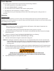
Prior to Operation The leveling system should only be operated under the following conditions: 1. The coach is parked on a reasonably level surface. 2. The coach “PARKING BRAKE” is engaged. 3. The coach transmission should be in the neutral or park position. 4. The ignition is in the run position, or engine is running. 5. Be sure all persons, pets and property are clear of the coach while Lippert Leveling System is in operation.
Manual Leveling Procedure Note: When leveling your coach, the coach should be leveled from FRONT TO REAR first (steps 2-4). When the coach is level from FRONT TO REAR, then level the coach from LEFT TO RIGHT (step 5). NOTE: Coach must be running for LCI Electronic/Hydraulic Leveling System to operate. 1. Push ON/OFF (Fig. 5O) button on control panel. The system is now operational and the ON/OFF (Fig. 5O) light will be lit. If ON/OFF (Fig. 5O) light is not lit, see PRIOR TO OPERATION, page 9. 2.
Manual Override for Bi-Rotational Power Units 1. Remove protective label (Fig. 9A). 2. Manually open jack valves with a 5/32" hex wrench (Fig. 7). 3. Using a 1/4" hex bit, insert into auxiliary drive device, i.e. cordless drill or power drill. 4. Insert hex bit into coupler found under protective label (Fig. 10). 5. Run drill forward or clockwise to extend jacks and in reverse or counterclockwise to retract jacks. 6. Close the manual override on the valves that were manually opened (Fig. 8). Fig.
Bi-Rotational Components A B D C H E F I J G K N M O L P R Callout A B C D E F G H I J K L M N O P Q R Rev: 07.14.
Fig. 11 - P/N 149086 A H D B J G B E I C F Manual Override Fig. 12 - P/N 149085 A H B D J C G E I F Manual Override Rev: 07.14.
Fig. 13 - P/N 149083 A H B D J C G E I F Manual Override Fig. 14 - P/N 149084 A H D C J G B E I F Manual Override Rev: 07.14.
Fig.15 - P/N 149087 A H B D J G C E I F Manual Override Fig. 16- P/N 145941 A H D B J G E I C F Manual Override Rev: 07.14.
Fig. 17 - P/N 179866 A H B J G B E I F Manual Override Rev: 07.14.
Wiring Diagram - Bi-Rotational Power Unit Harness Fig. 18 B A E D C Fig. 18C Fig. 18A Wire Color White White w/ Black Blue Green Yellow Red Brown Purple Grey Wire Color Purple Pink Red Blue Green Function 12v DC Power Pump Retract Curbside Rear Valve Roadside Front Valve PSI Switch Roadside Rear Valve Plug Curbside Front Valve Pump Extend Fig. 18D Wire Color White Black w/ White Brown Grey Black Fig.
Manual Override for Unidirectional Power Units In the event that the jacks or slideouts will not extend or retract, the valves can be manually overridden. THIS IS IN AN EMERGENCY SITUATION ONLY! By using a hex wrench to turn the manual override clockwise on the valve (Fig. 19), and a drill to operate the motor, the leveling jacks can then be retracted. Remember to turn the manual override completely counterclockwise (Fig.
5. Insert driver into coupler found under plastic cap (Fig. 22). 6. Run drill in reverse or counterclockwise to retract jacks (Fig. 23). 7. Replace connector to the directional valve. 8. Close the manual override on the valves that were manually opened (Fig. 20). Fig. 21 Connector Directional Valve Fig. 22 Fig. 23 A Plastic Cap (A) Rev: 07.14.2014 Run drill in reverse or counterclockwise to retract.
Uni-Directional Components A B C G F D E H I K L Callout A B C D E F G H I J K L Rev: 07.14.
Fig. 24 - P/N 196894 E C J F B K D G I H Manual Override Fig. 25 - P/N 197248 E A G F A D I Manual Override K H Rev: 07.14.
Fig. 26 - P/N 211166 E A G F D A J I Manual Override K H Fig. 27 - P/N 196895 E A J F D K A G I H Manual Override Rev: 07.14.
Fig. 28 - P/N 197247 E A G F D A J I K H Manual Override Fig. 29 - P/N 197249 E A G F D A J I K H Manual Override Rev: 07.14.
Fig. 30 - P/N 218311 E D A G F B C B K H Manual Override Rev: 07.14.
Wiring Diagram - Unidirectional Power Unit Harness Fig. 31 A C B Fig. 31A Wire Color White White w/ Black Blue Green Yellow Red Black Purple Grey Rev: 07.14.2014 Function 12v DC Power Pump Retract Curbside Rear Valve Roadside Front Valve PSI Switch Roadside Rear Valve Ground from solenoid Curbside Front Valve Pump Extend Wire Color Green Green Orange Purple Tan Fig. 31B Function LF Valve Isolator Valve Main Room Slide Curbside Front Valve Kitchen Slide Fig. 31C Wire Color Lt.
Automatic Safety Shutoff If the control panel is left on and inactive for four minutes it will shut off automatically. To reset the system the coach ignition must be turned off, then back on and the ON/OFF button must again be pushed. Drive Away Protection System If the ignition is in the “RUN” position, jacks are down, and the operator releases the parking brake, all indicator lights will flash and the alarm beeper will activate.
Maintenance Preventative Maintenance Procedures 1. Change fluid in reservoir only every 36 months. A. Check fluid only when jacks and slideouts are fully retracted. B. Always fill the reservoir with the jacks and slideouts in the fully retracted position. Filling reservoir when jacks are extended will cause reservoir to overflow into its compartment when jacks and slideouts are retracted. C. When checking fluid level, fluid should be within 1/4” of fill spout lip. 2. Check the fluid level every month.
Slideout Adjustment Fig. 32 A C B 2"-3" Free Travel Adjusting room so it seals in the "IN" position 1. Locate cylinder coming through the frame. 2. Run the room partially out. 3. Hold jam nut (Fig. 32A) in place with a wrench. 4. Adjust Nylock nut (Fig. 32C) towards the bracket if the room does not seal or adjust the Nylock nut (Fig. 32C) away from the bracket if the room is too tight and damages the fascia.
Troubleshooting Chart Problem System will not turn on and on/off indicator light does not illuminate. Control pad turns on but turns off when leg button is pushed. Control pad turns on, coach will not auto-level, "jacks down" light is on, jacks are retracted.
Troubleshooting Chart - HLG Problem Jacks will not extend to ground, pump is running. Probable Cause Little or no fluid in reservoir Leg valve is inoperative Electronic signal is lost between switch Hose damaged or disconnected. Return valve inoperative. Any one or two jacks will not retract. Electronic signal is lost between switch and solenoid. Corrective Action Fill reservoir with DEXRON III Clean, repair or replace Trace wires for voltage drop or loss of signal and leg valves.
The contents of this manual are proprietary and copyright protected by Lippert Components, Inc. (“LCI”). LCI prohibits the copying or dissemination of portions of this manual unless prior written consent from an authorized LCI representative has been provided. Any unauthorized use shall void any applicable warranty. The information contained in this manual is subject to change without notice and at the sole discretion of LCI. Revised editions are available for free download from www.lci1.com.