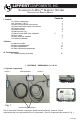
LIPPERTCOMPONENTS, INC. Schwintek In-Wall™ Slideout System Operation and Service Manual Contents I. Controls 1-1 System components 1 1-1A versions C1 & C2 2 1-2 Motor wiring harness connections 3 1-3 Extend and retract switch connections 3 1-4 Power to board 4 1-5 Board overview 4 1-6 Manual mode -jog 5 1-7 Manual mode -stall force calibration 5 1-8 Error codes 5 1-9 Motor direction switches 7 1-10 System schematic 7 II.
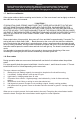
I. CONTROLS - VERSIONS C1 & C2 Version C1 maintains the same motor harness connector to the controller as in version C. However, the connector at the motor has been insulated with a new molded shield to protect against external damage. Version C2 motor harnesses have molex connectors at the controller and the molded connector at the motor end.Wire colors match with color codes on control board. NOTE: It doesn’t matter which motor is 1 or 2.
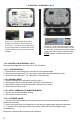
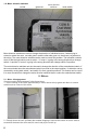
1-2 Motor wiring harness connections Correctly connected motor NOTE: Ribs on motor connector line up with notch in side of male connector on wiring harness. Color codes on wires also match (black to black, red to red, etc.). 1-3 Extend and retract switch connections NOTE: Direction control switch (customer supplied) Common connection on control board goes to common connection on extend and retract switch.
status led’s motor 1 connector motor direction direction switch switches mode button stall calibration power connection motor 2 connector Status led’s - 2 led’s, 1 green and 1 red, are provided to indicate current controller status and faults. Motor direction switches - Used to change direction of motors, 2 are provided, 1 for each motor. Mode button - Places controller in manual mode, for jogging individual motors.
Caution! During this override procedure the motors are not synchronized. Visually watch the room, if one side is moving significantly slower then the other (or not at all) then immediately stop and use the “motor disengagement” override method. 1-7 Stall force calibration If the system stalls out before reaching end of stroke, or if the room doesn’t seal as tightly as desired, then stall force may be increased.
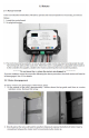
1-9 Motor direction switches red led green led motor direction switches mode switch Motor direction switches are used to change the direction of individual motors. If when trying to extend or retract the room, one side goes in and the other side goes out, then there is a problem in the wiring. The motor direction switches can be used to correct this problem. The left switch controls motor 2 and the right switch controls motor 1. If motor 1 is going in the wrong direction then change switch 1’s position.
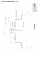
1-10 System schematic Revisions B - C - C1 7
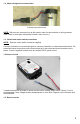
**********Do not move the rv unless the motors are plugged in.************* 3. Lift the motor approximately 1 inch, tighten the motor retention screw to hold the motor in it’s raised position. 4. The motor is now disengaged. Repeat these steps on the other side of the room. The room should move freely, and can be pushed in or out as desired. *************Do not move the rv with the motors disengaged.************* 5.
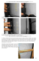
2-2 Motor replacement 1. If a motor needs replacement follow steps 1 through 4 for motordisengagement. 2. With the motor disengaged place support under the room. Wedges, a jack, or forklift may be used. 3. Once the room is supported, remove the screws retaining the side column to the outside face of the rv. 4. Slightly raise the room to remove any weight from the side column. It is now possible to slide the side column out of the wall, it may be necessary to use a pry bar to start the column moving.
*********Do not push shaft up further than 1 ½ inches.************ b. The coupler will be lifted above the motor mount and can be removed with a pair of needle nose pliers or hemostats. 7. The coupler needs to be placed onto the end of the drive shaft, inside the motor mount, at the top end of the column. Note the splines on the drive shaft and motor coupler. The coupler can be rotated while pushing down, or the side column can be pushed back and forth while pushing down, to engage the splines.
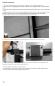
8. The motor can now be installed. Insert the motor through the top of the side column. Note the screws protruding from the shaft end of the motor. They enter into the 2 holes in the corners of the motor mount. Pay attention to the orientation of the screws and mating holes. 9. Align the motor shaft with the hole in the coupler, the motor should drop part of the way into the coupler.
11. Tuck the motor wires inside the side column. The column can be slid back along the racks, and into the opening in the wall. There will be some resistance from the motor. 12. With the side column mounting flange pushed against the outside of the wall, the mounting screws can be replaced. 13. Plug the motor back in. 2-3 Slide mechanism replacement 1. Follow steps 1 through 4 for motor replacement. 2.
The hook slides into a hook shaped slot on the top edge of the racks. The v-roller fits into a v shaped grove on the bottom edge of the rack. The gear meshes with the rack teeth on the outside face of the rack. Start the top hook on the side column into the hooked slot on the top gear rack on the side of the room. Start the bottom hook on the side column into the sthooked slot on the bottom gear rack on the st side of the room.
3-1 Trouble shooting flow chart III.
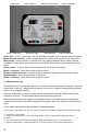
3-2 Checking Fuses The Total Control 1Slide requires a minimum of 30 amp fuse. Check the 12 volt fuse box for blown fuses, and replace any if necessary. Consult the rv manufacturers documentation for the location of the 12 volt fuse box, and the location of the Room Slide Controller’s fuse. If the fuse blows immediately upon replacement, there is a problem with the wiring to the In-Wall™ Slide control box. Have qualified service personnel check and repair.