HYDRO-SYNC SLIDEOUT SYSTEM OPERATION AND SERVICE MANUAL
TABLE OF CONTENTS SYSTEM……………………………………………........….…..3 Warning…………………………………........……....3 Description………………………………........……..3 Prior to Operation…………………….......……… 4 4 OPERATION…………………………………........…………… Main Components........................................ 5 Mechanical...................................... 5 Electrical......................................... 5 Operating System...................................... 5 Extending Slideout Room…............ 6 Retracting Slideout Room……........
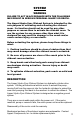
SYSTEM WARNING FAILURE TO ACT IN ACCORDANCE WITH THE FOLLOWING MAY RESULT IN SERIOUS PERSONAL INJURY OR DEATH. The Lippert Hydro-Sync Slideout System is intended for the sole purpose of extending and retracting the slideout room. Its function should not be used for any other purpose or reason than to actuate the slideout room. To use the system for any reason other than what it is designed for may result in damage to the coach and/or cause serious injury or even death.
PRIOR TO OPERATION Prior to operating the Lippert Hydro-Sync Slideout System, follow these four (4) guidelines: 1. Coach should be parked on the most level surface available. 2. The PARKING BRAKE must be engaged. 3. The coach’s transmission must be in NEUTRAL or PARK. 4. The coach’s ignition must be in the RUN position or the coach’s engine must be running.
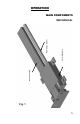
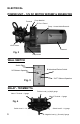
Inner Assembly Outer Assembly Hydraulic Cylinder OPERATION MAIN COMPONENTS MECHANICAL Fig.
ELECTRICAL POWER UNIT – 12V DC MOTOR W/PUMP & RESERVOIR Pump Manifold Trombeta “E” Port - Extend Pump – Housed inside Reservoir 12V DC Motor Reservoir Fig. 2 Pump Switch WALL SWITCH Switch Plate “IN” Slideout Operation Bi-directional Rocker Switch “OUT” Slideout Operation Fig. 3 RELAY - TROMBETTA Positive Lead (+)-(Hot) 6 gauge Motor 1 Terminal – 6 gauge Motor 2 Terminal – 6 gauge Fig.
OPERATING SYSTEM WARNING FAILURE TO ACT IN ACCORDANCE WITH THE FOLLOWING MAY RESULT IN SERIOUS PERSONAL INJURY OR DEATH. ALWAYS MAKE SURE THAT THE SLIDEOUT ROOM PATH IS CLEAR OF PEOPLE AND OBJECTS BEFORE AND DURING OPERATION OF THE SLIDEOUT ROOM. ALWAYS KEEP AWAY FROM THE SLIDE RAILS WHEN THE ROOM IS BEING OPERATED. THE GEAR ASSEMBLY MAY PINCH OR CATCH ON LOOSE CLOTHING CAUSING PERSONAL INJURY. INSTALL TRANSIT BARS (IF SO EQUIPPED) ON THE SLIDEOUT ROOM DURING STORAGE AND TRANSPORTATION.
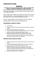
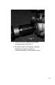
C B Fig. 5 MANUAL OPERATION The Lippert Hydro-Sync Slideout System can be run with auxiliary power devices like electric drills, ratchet wrenches or cordless screwdrivers. In the event of electrical or system failure, this manual method of extending and retracting the slideout room can be used. A standard handheld drill is all that is required. A standard 38" room will take approximately 45 seconds to retract. See the instructions below. Fig. 6 1. Remove protective label. (See Fig 6). 8 2.
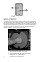
Fig. 7 3. Insert hex bit into coupler found under protective label. (See Fig. 7) 4. Run drill forward or clockwise to extend slideout room and in reverse or counterclockwise to retract slideout room.
PREVENTATIVE MAINTENANCE The Lippert Hydro-Sync Slideout System has been designed to require very little maintenance. To ensure the long life of your slideout system, read and follow these few simple procedures. WARNING DO NOT WORK ON YOUR SLIDEOUT SYSTEM UNLESS THE BATTERY IS DISCONNECTED. FAILURE TO ACT IN ACCORDANCE WITH THE FOLLOWING MAY RESULT IN SERIOUS PERSONAL INJURY OR DEATH.
Note: The Lippert Hydro-Sync Slideout System is designed to operate as a negative ground system. A negative ground system utilizes the chassis frame as the ground source. An independent ground wire back to the battery is not needed. It is important the electrical components have good wire to chassis contact. To ensure the best possible ground, a star washer should be used. Over 90% of unit electrical problems can be attributed to bad ground connections.
SERVICE FLUID FILLING PROCEDURE Breather/Fill Cap Fig. 8 The Lippert Hydro-Sync Slideout System uses automatic transmission fluid (ATF). Any ATF can be used. A full synthetic or synthetic blend works best such as Dexron III or Mercon 5. For best operation, fill system within ½” of the top when all slideouts are completely retracted. The see through reservoir makes it easy to check oil level. It is recommended that the oil level be checked prior to operating the system.
TROUBLESHOOTING The Lippert Hydro-Sync Slideout System is only one of four interrelated slideout room system components. These four components are as follows: chassis, slideout room, coach and Lippert Hydro-Sync Slideout System. Each one needs to function correctly with the others or misalignment problems will occur. Every coach has it’s own personality and what may work to fix one coach may not work on another even if the symptoms appear to be the same.
TROUBLESHOOTING CHART The following troubleshooting chart outlines some common problems, their causes and possible corrective actions. When reference is made to a “Power Unit,” the term includes the motor and the actuator as a complete unit. All Power Units are shipped from the factory with a serial number and date code, which should be given to the service technician when asking for assistance.
TROUBLESHOOTING – POWER UNIT Before attempting to troubleshoot the Power Unit, make sure an adequate power source is available. The unit batteries should be fully charged or the unit should be plugged into to A/C service with batteries installed. Do not attempt to troubleshoot the Power Unit without assuring a full 12V DC charge The following tests require only a DC voltmeter (or DC test light) and a jumper lead.
TROUBLESHOOTING – CHECKING FOR BAD CYLINDER 1. Retract (close) the slideout (room) completely. 2. Loosen hose from “E” (extend) port on the manifold of the Power Unit. WARNINGDo not attempt to run room out with the “E” port hose loose. The system will experience RAPID FLUID LOSS. 3. Plug opening on manifold to prevent drawing air into the system. 4. Energize the Power Unit to retract (close) room. 5. Continue to run the room in and watch for fluid flow from hose/port “E”.
MOTOR - TROMBETA BATTERY 10 GA WIRE MINIMUM 50 AMP AUTO-RESET BREAKER CHANGE OF POLARITY REVERSES MOTOR OUT IN Green – 16 gauge No wires connected to this side of switch Red “Hot” – 16 gauge Yellow – 16 gauge Fig.
ORDERING PARTS To assist the customer service when ordering parts, please provide the following information: 1. Your Name 2. Company Name 3. Phone Number 4. Shipping Address 5. Billing Address 6. Purchase Order Number 7. Coach A. Serial # and/or VIN # B. Make C. Model 8. Part Number 9. Description 10. Quantity Please take your coach to an authorized service center for repairs.