Hydraulic Through Frame Slideout OWNER'S MANUAL Rev: 07.09.
TABLE OF CONTENTS Warning, Safety, and System Requirement Information Description Safety Information Prior to Operation Operation Extending Slideout Room Retracting Slideout Room Maintenance Inspection System Maintenance Electrical System Maintenance Mechanical Maintenance Troubleshooting Troubleshooting Introduction Hydraulic slideout cylinder retract test Hydraulic slideout cylinder extend test Fluid Filling Procedure Comparing 14.
2x2 Hydraulic Through Frame Slideout Assembly 2x2 Hydraulic Through Frame Slideout Components 2x2 Hydraulic Through Frame Slideout Components 2x2 Hydraulic Through Frame Slideout Components 2x2 Hydraulic Through Frame Slideout Drive Components 2x3 Hydraulic Through Frame SLideout Assembly 2x3 Hydraulic Through Frame Slideout Assembly 2x3 Hydraulic Through Frame Slideout Components 2x3 Hydraulic Through Frame Slideout Drive Components 2.5x2.5 Hydraulic Through Frame Slideout Assembly 2.5x2.
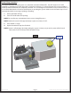
Warning, Safety, and System Requirement Information Description The Lippert Hydraulic Through Frame Slideout System is a rack and pinion guide system, utilizing a hydraulic cylinder to move the room assembly. The power unit drives the cylinder rod in a forward and backward motion to move the slide room in and out. The Lippert Hydraulic Slideout System is designed to operate as a negative ground system.
Prior to Operation Prior to operating the Lippert Hydraulic Through Frame Slideout System, follow these guidelines: 1. Coach should be parked on the most level surface available. 2. Leveling or stabilizing system should be actuated to ensure coach will not move during operation of slideout system. 3. Be sure battery is fully charged. 4. Be sure to keep all persons and pets clear of slideout system during operation.
Maintenance Inspection After servicing the slideout system in any way, be sure to check the following: 1. Slideout stops are installed and adjusted properly. 2. Head assemblies are installed and adjusted properly. 3. System is mounted properly. 4. Cross shafts are mounted properly and clear all other components. 5. Gear packs function properly. 6. Manual override is accessible. 7. Outside seals compress when slideout is retracted. 8. Inside seals compress when slideout is extended. 9.
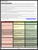
Troubleshooting Troubleshooting Introduction This troubleshooting chart outlines some common problems, their causes and possible corrective actions. If any part or serial number information is available, provide it to the service technician when asking for assistance. The Lippert Slideout System is only one of four interrelated slideout room system components. These four components are: chassis, room, coach, and Lippert Slideout System.
Hydraulic slideout cylinder retract test 1. Retract (close) all slideouts (rooms) completely. 2. Disconnect all rooms from system (if coach is equipped with IRC, close all but one room). 3. Loosen hose from "E" (extend) port on the manifold of the power unit. 4. Plug opening on manifold to prevent drawing air into the system. Do not attempt to run room out with the "E" port hose loose. The system will experience rapid fluid loss. 5. Energize the pump unit to retract (close) room. 6.
Fluid Filling Procedure The Lippert Hydraulic Slideout System uses automatic transmission fluid (ATF). Any ATF can be used. A full synthetic or synthetic blend works best such as Dexron III or Mercon 5. For best operation, fill system to within ½” of the top when all slideouts are completely retracted. The see-through reservoir makes it easy to check oil level. It is recommended that the oil level be checked prior to operating the system.
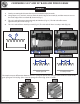
COMPARING 14.5° AND 20° RACK AND PINION GEARS SLIDEOUTS 1. Start by measuring the distance between two individual adjacent teeth. 2. Using calipers or a steel rule, measure from the inside edge of one tooth (A), and then measure over to the inside edge of the next tooth (B) shown in (Fig. 1). 3. The 14.5° rack will measure approximately 0.170 inches (Fig. 2.1). The 20° rack will measure approximately 0.231 inches (Fig. 3.1). 4. The 14.5° rack will have 4 teeth per inch (Fig 2.2).
GEAR PACK REPLACEMENT INSTRUCTIONS SLIDEOUTS In the event a gear pack needs to be replaced, follow these steps: 1. Run slideout room half way out. 2. Place a jack under the inner arm of the slideout. 3. Jack room up just enough to remove pressure off the gear pack. 4. Remove drive bolt from the cross shaft. 5. Remove bolts which hold the gear pack assembly in place on the outer rail. 6. Drop out the damaged gear pack. 7. Install the new gear pack. 8.
CORRECTIVE ACTION FOR SQUEAKING GEAR PACKS SLIDEOUTS Fig. 1 Fig. 2 A A B Fig. 3 Fig. 4 A A B C 1. Loosen both gear packs bolts (Fig. 1A and Fig. 1B) until tension is off of the gear pack. 2. Using a manual pump oil can, pump 2-3 squints of synthetic motor oil onto gear pack drive shaft in lubrication points (Fig. 2A), (Fig. 3A), (Fig. 4 A through D). D Note: Do not lubricate rack or pinion gear teeth, lubricate drive shaft only.
Motor troubleshooting Before attempting to troubleshoot the motor, make sure an adequate power source is available. The unit batteries should be fully charged or the unit should be plugged into A/C service with batteries installed. Do not attempt to troubleshoot the motor without assuring a full 12V DC charge. The following tests require only a DC voltmeter (or DC test light) and a jumper lead. 1. Attach voltmeter (or test light) leads to the negative and positive switch terminals on back of wall switch.
Rev: 07.09.
ROOM BAR MEASUREMENT CHART SLIDEOUTS Instructions: 1. Circle which side of your coach this room bar is for (Door Side or Off Door Side). 2. Enter the measurements for A, B, C, and D on the lines at the bottom. FRONT OF COACH DOOR SIDE Room Bar OFF DOOR SIDE Room Bar D C A B Brackets A________ Rev: 07.09.
Adjusting room so it seals in the IN position 1. Locate cylinder coming through the frame. 2. Run room partially out. 3. Hold Jam nut (Fig. 1A) in place with wrench. 4. Adjust Nylock nut (Fig. 1C) towards the bracket if the room does not seal or adjust the Nylock nut (Fig. 1C) away from the bracket if the room is too tight and damages the fascia. Note: Make small adjustments running the room in after each adjustment until proper seal is achieved. Adjusting room so it seals in the OUT position 1.
Mechanical Room Adjustment Note: All slideout room adjustments must be performed by certified service technicians. Adjustments made by non-certified persons may void any and all warranty claims. Horizontal adjustment 1. Loosen carriage bolts (Fig. 2A) on each bracket located at the end of each guide tube. 2. Room is ready to be positioned horizontally by pushing on the outside, sidewall or by using a prying device inserted into the opening between the room and coach.
Extend and retract cylinder port locations Standard Slideout Cylinder Extend Retract Rod End Piston Rod Cap End Stud Trunnion Slideout Cylinder Retract Extend Rod End Piston Rod Cap End Stud Manual Override The Lippert Hydraulic Slideout System can be run with auxiliary power devices like electric drills, ratchet wrenches or cordless screwdrivers. In the event of electrical or system failure, this manual method of extending and retracting the slideout room can be used.
2X2 HYDRAULIC THROUGH FRAME SLIDEOUT ASSEMBLY SLIDEOUTS Outer Tube Assembly Inner Tube Assembly Stiffener Head Assembly Hat Gear Pack Assembly Rear Roller Wear Pad Roller Shaft Inner Tube Assembly Spur Gear Rev: 07.09.
2X2 HYDRAULIC THROUGH FRAME SLIDEOUT COMPONENTS SLIDEOUTS B A E C D G F H K J L I Callout A B C D E F G H I J K L Rev: 07.09.
2X2 HYDRAULIC THROUGH FRAME SLIDEOUT COMPONENTS SLIDEOUTS B A D C F E Note: See Room Bar Measurement Chart (LIP Sheet 0080) G Callout A B C D E F Part # Description 104851 Slideout Mounting Bracket 141792 1 3/8" Adjustable Head Assembly 159624 Standard Weld-On Head Assembly 163049 Flush Adjustable Head Assembly 173593 Standard Flush Fixed Head Assembly 173594 Standard Flush Adjustable Head Assembly 183949 Room Bar (Use for up to 80") G 183950 Room Bar (Use for up to 154") Note: Brackets can be shi
2X2 HYDRAULIC THROUGH FRAME SLIDEOUT COMPONENTS SLIDEOUTS A B D G Callout Rev: 07.09.
2X2 HYDRAULIC THROUGH FRAME SLIDEOUT DRIVE COMPONENTS SLIDEOUTS A B C E D F G Callout A B C D E F G Rev: 07.09.
2X3 HYDRAULIC THROUGH FRAME SLIDEOUT ASSEMBLY PRODUCT CATEGORY 2 x 3 Shorty Hydraulic Slideout Hydraulic Cylinder Cylinder Mounting Bracket Outer Arm Assembly Roller Rod & Pin Inner Arm Assembly Front Roller Assembly Section Assembly Wear Tab Rear Roller Roller Shaft Front Roller Rev: 07.09.
2X3 HYDRAULIC THROUGH FRAME SLIDEOUT ASSEMBLY SLIDEOUTS 2 x 3 Bolt-In Hydraulic Slideout See Page 1 for Component Descriptions 2 x 3 Full Wall Hydraulic Slideout See Page 1 for Component Descriptions Idler Arm Rev: 07.09.
2X3 HYDRAULIC THROUGH FRAME SLIDEOUT COMPONENTS SLIDEOUTS B A D G C Callout H A I B J K Rev: 07.09.
2X3 HYDRAULIC THROUGH FRAME SLIDEOUT DRIVE COMPONENTS SLIDEOUTS B A C G F E D H Callout A B C D E F G H Rev: 07.09.
2.5X2.5 HYDRAULIC THROUGH FRAME SLIDEOUT ASSEMBLY SLIDEOUTS Inner Arm Assembly Outer Arm Assembly Gear Pack Assembly Rear Cylinder Mounting Bracket Cross Shaft Kit Head Assembly Hydraulic Cylinder Front Cylinder Mounting Bracket Section View Wear Tab Rear Roller Spur Gear Rev: 07.09.2014 Page 28 2.5x2.
2.5X2.5 HYDRAULIC THROUGH FRAME SLIDEOUT COMPONENTS SLIDEOUTS B A C E D F H J I Callout A B C D E F G H I J K Rev: 07.09.2014 G K Part # 122837 123356 105892 103480 277882 101941 328044 113535 106040 106030 102357 Description Gear Pack (Standard) Gear Pack (Heavy Duty) Rear Roller Wear Tab Wear Tab for 317322 Spur Gear Spur Gear Heavy Duty Front Cylinder Bracket Rear Cylinder Bracket Trim Plate Stiffener Page 29 2.5x2.
2.5X2.5 HYDRAULIC THROUGH FRAME HEAD ASSEMBLIES (STANDARD) SLIDEOUTS A F E D C B H G I Callout A B C D E F G H I Rev: 07.09.
2.5X2.5 HYDRAULIC THROUGH FRAME HEAD ASSEMBLIES (V-TECH) SLIDEOUTS A D F E I Part # 118127 119157 123999 124000 145388 145389 146612 151474 151475 180461 105966 103139 H G J Callout A B C D E F G H I J K L Rev: 07.09.
2.5X2.5 HYDRAULIC THROUGH FRAME SLIDEOUT COMPONENTS SLIDEOUTS B A C D E Callout Rev: 07.09.2014 Part # Description 143674 Outboard Outer Arm (Idler) A 143675 Outboard Outer Arm (Drive) B 143707 Outboard Inner Arm 143676 Inboard Outer Arm (Idler) C 143677 Inboard Outer Arm (Drive) D 143710 Inboard Inner Arm E 296121 Inboard Inner Arm (18 Teeth) F 317322 Outboard Inner Arm (18 Teeth) Note: Standard slideout arms have 15 teeth. Page 32 F 2.5x2.
2.5X2.5 HYDRAULIC THROUGH FRAME SLIDEOUT DRIVE COMPONENTS SLIDEOUTS D E F Callout A B C D E F G Rev: 07.09.2014 C B A Part # 123603 125653 133874 141109 173738 120639 140530 G Description Hydraulic Cylinder 38" Hydraulic Cylinder 24" Hydraulic Cylinder 30" O-Ring Face Seal Straight Fitting O-Ring Face Seal Elbow Fitting Hydraulic Interior Slideout Switch 6 Prong Interior Switch with Wall Plate Page 33 2.5x2.
Notes Rev: 07.09.
Rev: 07.09.
All information contained within may be distributed as a full document only, unless otherwise permitted by explicit consent of Lippert Components Inc. to distribute individual parts. All information contained within is subject to change without notice. New editions will be posted on www.lci1.com and can be downloaded for free. Information contained within is considered factual until made obsolete by a *NEW* revision. Please recycle all obsolete materials.