G����� C������ 3.0 TROUBLESHOOTING GUIDE Rev: 01.30.2015 Page 1 Ground Control 3.
GROUND CONTROL 3.0 TROUBLESHOOTING GUIDE TABLE OF CONTENTS Introduction Components Operation 3 3 6 6 6 7 7 8 8 9 9 9 11 12 Basic Jack Operation Auto Level Auto Level Sequence Hitch Recognition Homing Jacks Zero Point Calibration Troubleshooting - Touch Pad Special Jack Error Codes Touch Pad Error Codes 4 - Point Wiring Diagram 6 - Point Wiring Diagram Rev: 01.30.2015 Page 2 Ground Control 3.
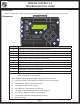
GROUND CONTROL 3.0 TROUBLESHOOTING GUIDE Introduction Ground Control 3.0 is an Automatic Electric Leveling system. The jacks in this system work in pairs. Fig. 1 - Touch Pad Components A K E B G C H F D I J Callout Description A Up Arrow - Scrolls up through the menu on LCD. B Down Arrow - Scrolls down through the menu on LCD. C Enter - Activates modes and procedures indicated on LCD. D Retract - Places leveling system into retract mode. E LCD Display - Displays procedures and results.
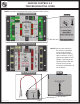
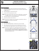
GROUND CONTROL 3.0 TROUBLESHOOTING GUIDE NOTE: Orientation is imperative for proper operation of the system. Fig. 2 - 4 Point Controller Fig. 2A Fig. 3 - 6 Point Controller NOTE: Some 6-point controllers do not have orientation arrows for the front of the unit. When installing those controllers, ensure that the port labeled "LEFT FRONT" is pointing to the left-hand front of the unit. This will ensure proper orientation and function of the controller. Fig. 4 - Rear Sensor Rev: 01.30.2015 Fig.
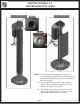
GROUND CONTROL 3.0 TROUBLESHOOTING GUIDE Fig. 5 - Landing Gear Fig. 6 - Leveling Jack Fig. 5A Fig. 6A NOTE: The Ground Control 3.0 Landing Gear (Fig. 5) and Leveling Jack (Fig. 6) both have a manual override on the top of the gearbox (Fig. 5A) and on the bottom of the motor (Fig. 6A). A. The manual override on the top of the gearbox (Fig. 5A) can be manually operated by a 3⁄8" drive ratchet and extension (no socket). B. The manual override on the bottom of the motor (Fig.
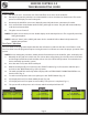
GROUND CONTROL 3.0 TROUBLESHOOTING GUIDE Operation Basic Jack Operation Landing gear jacks can be operated any time the system is “ON”. By pushing the “FRONT” button (Fig. 1G), both front or landing gear jacks can be extended. By pushing either the "FRONT" and “LEFT” (Fig. 1H) or "FRONT" and “RIGHT” (Fig. 1I) buttons, the individual front jacks can be extended. If the touch pad is put in the retract mode, indicated by the orange illuminated LED next to the “RETRACT” button (Fig.
GROUND CONTROL 3.0 TROUBLESHOOTING GUIDE Fig. 7 Auto Level Sequence 1. Front landing gear retract, lowering the front of the unit below level, stopping, then lifting the front end to level the unit front to back and left to right. (Fig. 7A). 2. Rear leveling jacks are grounded (Fig. 7B). 3. A side to side leveling sequence occurs. A NOTE: At this point on the 6-Point system, the two middle jacks are grounded to stabilize the unit. These two jacks do not level the unit (Fig. 7C). 4.
GROUND CONTROL 3.0 TROUBLESHOOTING GUIDE Homing Jacks 1. Introduce an error - disconnect one of the hall effect sensor wires at the controller. 2. Attempt to operate the jack that is associated with the sensor wire that was disconnected. The touch pad screen will display an error for that jack. 3. Reconnect the hall effect sensor wire. Manually extend all jacks down a minimum of 6 inches. 4. Press and hold the retract button until all of the jacks begin to retract.
GROUND CONTROL 3.0 TROUBLESHOOTING GUIDE Troubleshooting - Touch Pad Special Jack Error Codes To clear one of these errors: 1. Correct or otherwise repair the issue (see the table below). 2. Extend all of the jacks at least six (6) inches, then press and hold the “RETRACT” button on the touch pad until the jacks begin retracting. 3. All of the jacks will retract fully to clear the error.
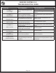
GROUND CONTROL 3.0 TROUBLESHOOTING GUIDE LCD Message ****ERROR**** Low Voltage ****ERROR**** Out Of Stroke ****ERROR**** External Sensor ****ERROR**** Jack Time Out ****ERROR**** Auto Level Fail ****ERROR**** Bad Calibration ****ERROR**** Internal Sensor **PANIC STOP** Function Aborted Rev: 01.30.2015 What's Happening? Battery voltage dropped below 10.8V. What Should Be Done? Check wiring for loose connection. Test battery voltage under load - charge or replace.
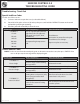
GROUND CONTROL 3.0 TROUBLESHOOTING GUIDE 4 - Point Wiring Diagram Circuit Interruption Battery NOTE: LEFT refers to roadside; RIGHT refers to curbside. Rev: 01.30.2015 Page 11 Ground Control 3.
GROUND CONTROL 3.0 TROUBLESHOOTING GUIDE 6 - Point Wiring Diagram Battery Rev: 01.30.2015 Page 12 Circuit Interruption Ground Control 3.
All information contained within may be distributed as a full document only, unless otherwise permitted by explicit consent of Lippert Components Inc. to distribute individual parts. All information contained within is subject to change without notice. New editions will be posted on www.lci1. com and can be downloaded for free. Information contained within is considered factual until made obsolete by a *NEW* revision. Please recycle all obsolete materials.