Ground Control 3.0 4 Point and 6 point OWNER'S MANUAL Rev: 01.28.2015 Page 1 Ground Control 3.
TABLE OF CONTENTS System and Safety Information Prior to Operation Touch Pad Diagram Operation Basic Jack Operation Unhitching from a Tow Vehicle Auto Level Auto Level Sequence Hitch Recognition Homing Jacks Zero Point Calibration Manual Override - Top of Jack Motor Manual Override - Bottom of Jack Motor Preventive Maintenance Special Jack Error Codes Troubleshooting - Touch Pad Ground Control 3.0 OEM Assembly Ground Control 3.
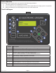
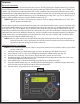
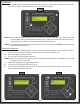
Prior to Operation The leveling system should only be operated under the following conditions: 1. The unit is parked on a reasonably level surface. 2. Be sure all persons, pets, and property are clear of the coach while the leveling system is in operation. 3. Make sure battery(ies) are fully charged and test at 12+VDC under load. Touch Pad Diagram Fig. 1 A E K B G C D H F I J Callout A B C D E F G H I J K Rev: 01.28.2015 Description Up Arrow - Scrolls up through the menu on LCD.
Operation Basic Jack Operation Landing gear jacks can be operated any time the system is “ON”. By pushing the “FRONT” button (Fig. 1G), both front or landing gear jacks can be extended. By pushing either the "FRONT" and “LEFT” (Fig. 1H) or "FRONT" and “RIGHT” (Fig. 1I) buttons, the individual front jacks can be extended. If the touch pad is put in the retract mode, indicated by the orange illuminated LED next to the “RETRACT” button (Fig.
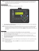
Auto Level 1. After unhitching from tow vehicle and parking the vehicle at a safe distance away from the unit, press the “ON/OFF” button (Fig. 3A) and then press “AUTO LEVEL” (Fig. 3B). Fig. 3 A B Note: Once the automatic leveling cycle has been started, it is important that there is no movement in the coach until the unit has completed the leveling process. Failure to remain still during the leveling cycle could have an effect on the performance of the leveling system.
Note: If the AUTO LEVEL sequence does not perform as described, place the system in manual mode and test that the jacks operate correctly by pushing their coordinating buttons on the touch pad; i.e. FRONT button operates only the front jacks. Hitch Recognition 1. 2. Turn on the touch pad. Press the left and right buttons simultaneously (Fig. 6A/B). Fig. 6 A 3.
Zero Point Calibration The “Zero Point” is the programmed point that the unit will return to each time the Auto Level feature is used. The “Zero Point” MUST be programmed prior to using the Auto Level feature to ensure the proper operation of the system. Note: Prior to starting this procedure, double check all connections on the controller, jacks, and touch pad. 1. Manually run the jacks to level the unit.
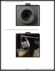
Manual Override - Top of Jack Motor Note: Use of a 12V-18V cordless screw gun or pneumatic screw gun is acceptable to manually override the jacks. Do not use an impact screw gun to perform the override procedure, as this may damage the motor. If manual override is necessary on any jack in the system, there are two options. The following process will describe how to use the top override. See Page 10 for the bottom override. Tools needed: 3/8” drive ratchet and extension (no socket) 1.
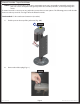
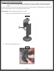
3. Insert the 3/8” drive into the port (Fig. 12). Fig. 12 4. Turn override until the jack extends or retracts to desired position (Fig. 13). Fig. 13 Rev: 01.28.2015 Page 9 Ground Control 3.
Manual Override - Bottom of Jack Motor Note: Use of a 12V-18V cordless screw gun or pneumatic screw gun is acceptable to manually override the jacks. Do not use an impact screw gun to perform the override procedure, as this may damage the motor. If manual override is necessary on any jack in the system, there are two options. The following process will describe how to use the bottom override. See Page 8 for the top override. Tools needed: 3/8” drive ratchet and extension, 5/16” socket 1.
3. Insert the 5/16” socket into the port (Fig. 16). Fig. 16 4. Turn override until the jack extends or retracts to desired position (Fig. 17). Fig. 17 Rev: 01.28.2015 Page 11 Ground Control 3.
Preventive Maintenance 1. 2. Remove dirt and road debris from jacks and stabilizer struts (if equipped) as needed. If jacks are down for extended periods, it is recommended to spray exposed leveling jack tubes with a spray lubricant every 3 months for protection. If the coach is located in a salty environment, it is recommended to spray the rods every month. Ensure the coach is supported at both the front and rear with jack stands before performing any troubleshooting or service to the unit.
Troubleshooting - Touch Pad Note: To clear an error from the touch pad, repair or otherwise correct the issue, then press “ENTER.” If the error is still present, the message will be displayed again. LCD Message What's Happening? Controller not properly secured. Excessive angle reached during auto operation. Controller not properly secured. Excessive angle reached during manual operation. Front of coach below level when starting Auto Level process (only when trying to initiate Hitch Recognition).
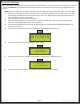
GROUND CONTROL 3.0 OEM ASSEMBLY LEVELING AND STABILIZATION Jack Mounting Bolt Hall Effect Jack; Rear Left Jack Mounting Nut Snapper Pin Bolt On Pull Pin Landing Gear Carriage Bolt Hall Effect Jack; Rear Right Jack Mounting Bracket Landing Gear Harness Top Lock Nut Controller LCD Touch Pad Power and Ground Harness Rear Sensor Rear Jack Harness Rev: 01.28.2015 Rear Sensor Mounting Plate Page 14 Rear Sensor Harness LCD Touch Pad Harness Ground Control 3.
GROUND CONTROL 3.0 COMPONENTS LEVELING AND STABILIZATION A B E Callout A B C D E F G Rev: 01.28.2015 Part # 305340 305339 344792 342610 343758 119113 134989 C D F G Description Hall Effect Landing Gear; Front Stroke 19.8125" Hall Effect Jack; Rear Left 12.5" Stroke Hall Effect Jack; Rear Right 12.5" Stroke Hall Effect Jack; Rear Short 10.5" Stroke Hall Effect Jack Motor Bolt On Pull Pin Weld On Jack Mounting Bracket Page 15 Ground Control 3.
GROUND CONTROL 3.0 COMPONENTS LEVELING AND STABILIZATION L I K H J M Callout H I J K L M Rev: 01.28.2015 Part # 178210 118076 119073 125878 225598 231775 Description Jack Mounting Nut; 1/2" - 20 Jack Mounting Bolt; 1/2" - 20 x 1 1/2" Flange Top Lock Nut Carriage Bolt Snapper Pin; 3/8 x 3" Rear Sensor Mounting Plate Page 16 Ground Control 3.
GROUND CONTROL 3.0 COMPONENTS LEVELING AND STABILIZATION O P Q N S R T Callout N O P Q R S T U Rev: 01.28.2015 U Part # 232201 232937 243688 267401 234802 329164 304136 346005 Description Rear Sensor LCD Touch Pad Harness Rear Sensor Harness Linc Remote Charger LCD Touch Pad Linc Remote 4-Point Hall Effect Canbus Wireless Ground Control Controller 6-Point Hall Effect Ground Control Controller Page 17 Ground Control 3.
GROUND CONTROL 3.0 COMPONENTS LEVELING AND STABILIZATION V W Callout V W Rev: 01.28.2015 Part # 305115 306298 307489 307490 347012 347013 306176 Description Hall Effect Right Rear Sensor Harness Hall Effect Left Rear Sensor Harness Hall Effect Right Front Sensor Harness Hall Effect Left Front Sensor Harness Hall Effect Right Mid Harness Hall Effect Left Mid Harness Power and Ground Supply Harness Page 18 Ground Control 3.
The contents of this manual are proprietary and copyright protected by Lippert Components, Inc. (“LCI”). LCI prohibits the copying or dissemination of portions of this manual unless prior written consent from an authorized LCI representative has been provided. Any unauthorized use shall void any applicable warranty. The information contained in this manual is subject to change without notice and at the sole discretion of LCI. Revised editions are available for free download from www.lci1.com.