G����� C������ 3.0 4 P���� ��� 6 P���� OEM INSTALLATION MANUAL Rev: 01.30.2015 Page 1 Ground Control 3.
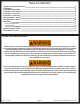
TABLE OF CONTENTS System and Safety Information Preparation Installation - Rear Jacks Installation - Rear Sensor Installation - Controller Installation - Touch Pad Wiring Diagram - 4 Point Wiring Diagram - 6 Point operation Basic Jack Operation Homing Jacks Zero Point Calibration Special Jack Error Codes Touch Pad Error Codes 2 3 3 4 7 8 9 10 11 11 11 12 12 13 System and Safety Information Failure to act in accordance with the following may result in death or serious personal injury.
Preparation 1. 2. Remove all loose items from the front storage compartments of the 5th wheel. Analyze the unit. Determine where the rear jack brackets, controller, and touch pad will be mounted on the unit. The rear jack brackets should be mounted approximately 1 foot behind the rear axle hanger and be aligned with each other. The controller should be mounted in the center of the unit in compliance with RVIA Gas Codes as the controller connections are not spark-proof.
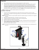
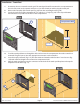
Installation - Rear Sensor The rear sensor (Fig. 2A) MUST be installed on the crossmember to the rear of the back axle, centered curbside to roadside on the unit with the arrows on the top of the sensor pointing the correct direction (Fig. 2 detail). Fig. 2 Fig. 2 Detail A 1. Dry fit the mounting plate (Fig. 3A) and the rear sensor (Fig. 3B) to the crossmember (Fig. 3C). The predrilled holes in the plate are for mounting the rear sensor to the plate. Mark on the plate where the rear sensor will set.
2. Attach the rear sensor (Fig. 4B) to the mounting plate (Fig. 4C) using two 3⁄8" hex head self-tapping screws (Fig. 4A). Orientation is imperative for the correct operation of the leveling system. Fig. 4 B C A 3. Attach the mounting plate (Fig. 5B) and sensor (Fig. 5C) assembly to the crossmember (Fig. 5D) using two 3⁄8" hex head self-tapping screws (Fig. 5A). Ensure that the plate is centered side to side on the frame and that the sensor is oriented properly (Fig. 5). Fig.
4. Connect the rear sensor harness to the connector on the rear sensor (Fig. 6A )and run the harness through the frame and up to the compartment where the controller will be mounted. Fig. 6 A Rev: 01.30.2015 Page 6 Ground Control 3.
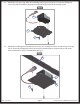
Installation - Controller NoTE: Prior to starting this portion of the installation, double check that all of the harnesses are properly and securely connected to the rear jacks, landing gear, and rear sensor. 1. Measure the ceiling of the compartment where the controller will be placed and mark the center point on the ceiling. The controller MUST be positioned directly in the center of the unit with the arrow on the label of the controller facing the front of the unit (Fig. 7).
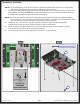
Installation - Touch Pad 1. 2. 3. Determine where to mount the touch pad. The touch pad should be mounted in a compartment on the side of the unit so the operator will have a view of the hitch pin while using the touch pad. Remove the faceplate of the touch pad (Fig. 9A) from the mounting bezel (Fig. 9B). Cut a hole in the wall of the compartment 3 3⁄8” wide by 2 ¾” high (Fig. 10) so the top and bottom horizontal cuts are parallel to the floor of the compartment. Fig. 9 Fig.
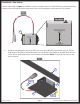
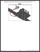
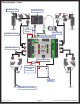
Wiring Diagram - 4 Point Hall Effect Jack LCD Touch Pad LCD Touch Pad Harness Rear Sensor Hall Effect Harness Rear Sensor Harness Hall Effect Harness 4 Point Controller oEM Supplied Circuit Interruption Battery Hall Effect Landing Gear Rev: 01.30.2015 Page 9 Ground Control 3.
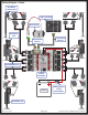
Wiring Diagram - 6 Point Hall Effect Landing Gear LCD Touch Pad Rear Sensor Hall Effect Jack Rear Sensor Harness Touch Pad Harness Hall Effect Harness 6 Point Controller Battery oEM Supplied Circuit Interruption Hall Effect Jack Rev: 01.30.2015 Page 10 Ground Control 3.
Touch Pad Diagram Fig. 13 A E K B G C D H F I J Callout A B C D E F G H I J K Rev: 01.30.2015 Description Up Arrow - Scrolls up through the menu on LCD. Down Arrow - Scrolls down through the menu on LCD. Enter - Activates modes and procedures indicated on LCD. Retract - Places leveling system into retract mode. - Press and hold down for 1 second to initiate Auto Retract. LCD Display - Displays procedures and results. Auto Level - Places leveling system into auto level mode.
operation Basic Jack Operation Landing gear jacks can be operated any time the system is “ON”. By pushing the “FRONT” button (Fig. 13G), both front or landing gear jacks can be extended. By pushing either the "FRONT" and “LEFT” (Fig. 13H) or "FRONT" and “RIGHT” (Fig. 13I) buttons, the individual front jacks can be extended. If the touch pad is put in the retract mode, indicated by the orange illuminated LED next to the “RETRACT” button (Fig.
Zero Point Calibration The “Zero Point” is the programmed point that the unit will return to each time the Auto Level feature is used. The “Zero Point” MUST be programmed prior to using the Auto Level feature to ensure the proper operation of the system. NoTE: Prior to starting this procedure, double check all connections on the controller, jacks, and touch pad. 1. Manually run the jacks to level the unit.
Touch Pad Error Codes Note: To clear an error from the touch pad, repair or otherwise correct the issue, then press “ENTER.” If the error is still present, the message will be displayed again.
The contents of this manual are proprietary and copyright protected by Lippert Components, Inc. (“LCI”). LCI prohibits the copying or dissemination of portions of this manual unless prior written consent from an authorized LCI representative has been provided. Any unauthorized use shall void any applicable warranty. The information contained in this manual is subject to change without notice and at the sole discretion of LCI. Revised editions are available for free download from www.lci1.com.