LCI B��� R��� ��� T��� C������ OWNER'S MANUAL Rev: 09.25.
TABLE OF CONTENTS System Description Prior To Operation Manual Slide-Out Bike Rack Operation Bike Rack Weight Ratings Maintenance Manual Fold-Down Bike Rack Operation Manual Loading of Bike Racks Manual Tire Winch Operation Spare Tire Holder Operation Spare Tire Carrier Weight Ratings Bike Rack Assemblies - Slide Out Bike Rack Assemblies - Fold Down Tire Carrier Assemblies - Winches Bumper Mounted Spare Tire Carriers 2 2 3 3 4 4 5 5 6 7 7 8 9 - 11 12 13 - 14 System Lippert bike rack and ti
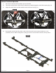
Prior To Operation 1. Remove all loose items from bicycles (pumps, bags, etc.) 2. Check that all quick release hubs are tight. The max load and rating per the applicable product is referenced on Page 4. The weight limit includes all items secured to the bumper, including mounting devices, attachment hardware, spare tires, bikes and load attaching devices. Manual Slide-Out Bike Rack Operation 1. Pull hair pin from cane bolt (Fig. 1). 2. Pull cane bolt from bike rack assembly.
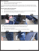
7. Release the snap pin and pull it from the stored mounting tube (Fig. 7). 8. Rotate the mounting tube vertically and place in the mounting bracket (Fig. 8). 9. Insert the snap pin completely through the mounting bracket and tube holes (Fig. 9). Fig. 7 Fig. 9 Fig. 8 10. Be sure the snap pin is securely fastened (Fig. 10). 11. Set the first bicycle on the bike rack up against the mounting tube (Fig. 11). 12.
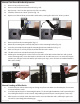
Manual Fold-Down Bike Rack Operation 1. Remove hair pin from cane bolt. 2. Remove cane bolt from bike rack bracket (Fig. 13A). 3. Repeat steps 1 and 2 on the opposite side of the assembly. 4. Fold bike rack into the "down" position (Fig. 14). 5. Replace cane bolt and hair pin into bike rack bracket, securing the rack in the "down" position. Fig. 14 Fig. 13 A 6. Remove pin from the mounting tube (Fig. 15). 7. Rotate the mounting tube vertically and place it in the mounting bracket (Fig. 16).
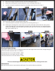
Manual Tire Winch Operation 1. Place the tire directly underneath the spare tire bracket. 2. Thread the winch portion of the of the tire bracket assembly through the wheel hub opening (Fig. 18). 3. Adjust the winch until it sits flush with the inside of the tire rim (Fig. 19). Fig. 18 4. Fig. 19 By using the manual crank (Fig. 20A) or with a hand wrench, lower (counter-clockwise) or raise (clockwise) the tire. While raising the tire, take great care to assure that the winch is still in position.
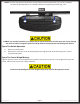
NOTE: The spare tire must be raised to the stow position by manual hand crank only. The tire should be raised to the point that the tire’s sidewall contacts the angle brackets firmly (Fig. 21A). Fig. 21 A A DO NOT over crank the winch or use a power drill or impact wrench to raise the spare tire. It may damage the winch or cable causing the spare tire to drop from its stowed position and damage the vehicle. Spare Tire Holder Operation 1. Remove mounting nuts. 2.
BIKE RACK ASSEMBLIES - SLIDE OUT STORAGE AND CONVENIENCE B A C Callout A B C Rev: 09.25.
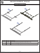
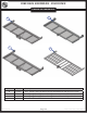
BIKE RACK ASSEMBLIES - FOLD DOWN STORAGE AND CONVENIENCE E D G F Callout D E Part # 180098 231815 F 253711 G 317467 Rev: 09.25.
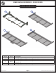
BIKE RACK ASSEMBLIES - FOLD DOWN STORAGE AND CONVENIENCE I H J Callout H I J K Rev: 09.25.
BIKE RACK ASSEMBLIES - FOLD DOWN STORAGE AND CONVENIENCE L M O N Callout L M N O Rev: 09.25.
TIRE CARRIER ASSEMBLIES - WINCHES STORAGE AND CONVENIENCE Q P Callout P Q Rev: 09.25.
BUMPER MOUNTED SPARE TIRE CARRIERS STORAGE AND CONVENIENCE S R T Callout R S T U Rev: 09.25.
BUMPER MOUNTED SPARE TIRE CARRIERS STORAGE AND CONVENIENCE V W Y X Callout V W X Y Rev: 09.25.
The contents of this manual are proprietary and copyright protected by Lippert Components, Inc. (“LCI”). LCI prohibits the copying or dissemination of portions of this manual unless prior written consent from an authorized LCI representative has been provided. Any unauthorized use shall void any applicable warranty. The information contained in this manual is subject to change without notice and at the sole discretion of LCI. Revised editions are available for free download from www.lci1.com.